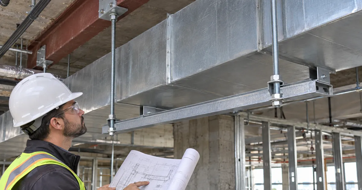
Horizontal rectangular duct hanger inspection verifies that installed rods, trapeze supports, hanger spacing, and structural attachments match approved project details and applicable manufacturer instructions.
- Use approved details applicable to the installed duct dimensions.
- Compare measured rod sizes, support arrangements, and hanger spacing with documented requirements.
- Check accessible anchorage and review evidence for required concealed installation attributes.
- Resolve deficiencies and unverifiable required attributes before accepting affected installations.
The checklist
Inspection Documents
- Confirm applicable approved support details are available and cover the installed duct dimensions, rod diameter, trapeze configuration, hanger spacing, and anchorage.
Missing or Conflicting Details
- Record missing or conflicting support requirements and refer them to the responsible designer for resolution before accepting the affected installation.
Anchor Installation Instructions
- Confirm applicable manufacturer installation instructions are available for the installed anchors or structural clamps.
Rod Diameter
- Measure hanger rod diameter using a method suitable for the rod type and compare its nominal size with the approved detail for the supported duct.
Rod Condition
- Inspect rods for visible bending, damaged threads, or corrosion; record defects for disposition before acceptance.
Trapeze Crossmember
- Verify crossmember material and section size match the approved trapeze detail.
Trapeze Configuration
- Verify rod number, rod locations, and crossmember orientation match the approved trapeze arrangement.
Duct Bearing
- Verify the duct bears on the trapeze as detailed, including any specified bearing pads or insulation protection, without visible local crushing or distortion.
Rod Connection Hardware
- Verify nuts, washers, and locking provisions at rod connections match the approved details.
Rod Thread Engagement
- Verify rod thread engagement at nuts, couplers, and threaded attachments against the applicable approved details or component manufacturer instructions.
Hanger Spacing
- Measure center-to-center distances between consecutive hangers and compare them with the approved spacing for the installed duct.
Special Support Locations
- Verify support locations at duct ends, changes in direction, branches, and inline equipment against applicable approved details.
Anchorage Substrate
- Verify each hanger attaches to the structural member or substrate identified in the approved anchorage detail.
Anchor or Clamp Selection
- Verify anchor or clamp type and size match the approved detail and are identified sufficiently to select the applicable manufacturer instructions.
Anchorage Placement
- Measure accessible anchor locations, spacing, and edge distances, or clamp positions, as applicable; compare them with approved details and applicable manufacturer instructions.
Visible Anchorage Condition
- Inspect accessible anchorage connections for missing hardware, visibly loose or displaced components, and cracking or other visible damage to the supporting substrate.
Installation Evidence
- Review installation records or other accepted evidence for required attributes that cannot be verified visually, such as anchor embedment and installation torque where specified.
Inspection Record
- Record each nonconforming or unverifiable hanger location, the applicable requirement, and the observed condition, with supporting measurements or photographs as appropriate.
Deficiency Closeout
- Before accepting an affected installation, verify that documented deficiencies and unverifiable required attributes have been resolved through correction and reinspection or documented disposition by the responsible designer.
Preview the printable checklist
Preview page one below. Open the image or download the PDF for all pages.

At a glance
- Approved support details establish the inspection criteria for the installed duct.
- Measurements and visual observations serve different purposes and should be recorded accordingly.
- Visible anchorage condition alone does not establish concealed attributes such as embedment.
- Acceptance depends on resolving documented discrepancies and unverifiable required attributes.
How to Use the Duct Hanger Inspection Checklist
- Establish the inspection basis using applicable approved support details and anchor or clamp instructions. Refer missing or conflicting requirements to the responsible designer.
- Use the approved checklist to guide field measurements and observations of rods, trapeze assemblies, duct bearing, connection hardware, spacing, and anchorage.
- Review installation records or other accepted evidence for required attributes that cannot be verified visually.
- Document nonconforming or unverifiable locations with the applicable requirement, observed condition, and supporting measurements or photographs as appropriate.
- Verify correction and reinspection or documented designer disposition before accepting an affected installation.
Start with the applicable support details
The inspection basis must cover the duct and support arrangement actually installed. Missing or conflicting requirements should be referred to the responsible designer rather than resolved through assumed rod sizes, spacing limits, or anchorage practices.
- Use details covering the installed duct dimensions, rods, trapeze configuration, spacing, and anchorage.
- Have the applicable anchor or structural clamp installation instructions available.
- Keep affected installations pending acceptance when requirements remain unresolved.
Assess the rods and trapeze as an assembly
A matching rod diameter does not, by itself, verify the support assembly. Crossmember size and orientation, rod locations, connection hardware, thread engagement, and duct bearing all contribute to whether the installation matches the approved arrangement.
- Compare nominal rod size using a measurement method suitable for the rod type.
- Distinguish dimensional discrepancies from visible defects such as bending, damaged threads, or corrosion.
- Evaluate duct bearing and any specified insulation protection against the approved detail.
Relate hanger spacing to the duct layout
Center-to-center measurements establish the spacing between consecutive hangers. The inspection also considers support locations at duct ends, changes in direction, branches, and inline equipment where applicable approved details address those conditions.
- Compare measured distances with the approved spacing for the installed duct.
- Do not assume that regular spacing alone verifies special support locations.
- Record the location and measurement of spacing discrepancies so they can be addressed.
Separate visible anchorage checks from installation evidence
Accessible anchorage can be checked for substrate, component selection, placement, and visible condition. Required attributes that cannot be confirmed visually need installation records or other accepted evidence. An apparently sound connection does not establish specified embedment or installation torque.
- Identify anchors or clamps sufficiently to select the applicable manufacturer instructions.
- Compare accessible placement measurements with approved details and applicable instructions.
- Treat missing evidence for a required concealed attribute as unresolved until appropriately closed out.
Make findings traceable through closeout
Useful inspection records connect each nonconforming or unverifiable hanger location to the applicable requirement and observed condition. Supporting measurements or photographs help explain the finding. Before acceptance, closeout requires correction and reinspection or documented disposition by the responsible designer.
- Identify affected locations clearly.
- Distinguish a confirmed discrepancy from an attribute that could not be verified.
- Verify resolution rather than treating a recorded finding as a completed closeout.