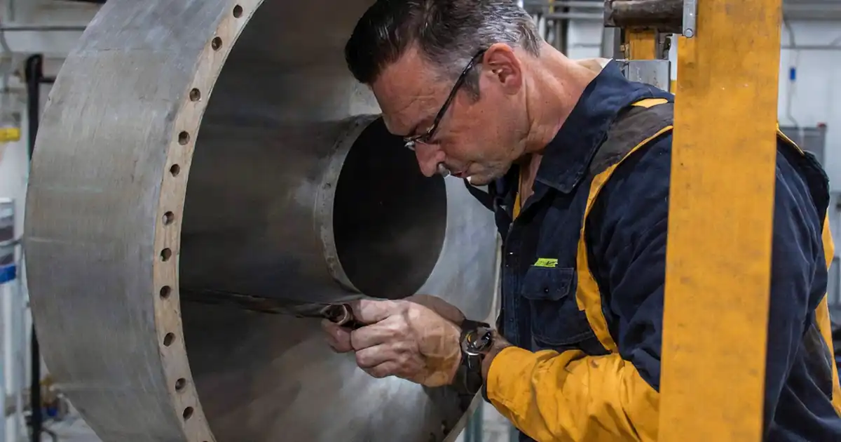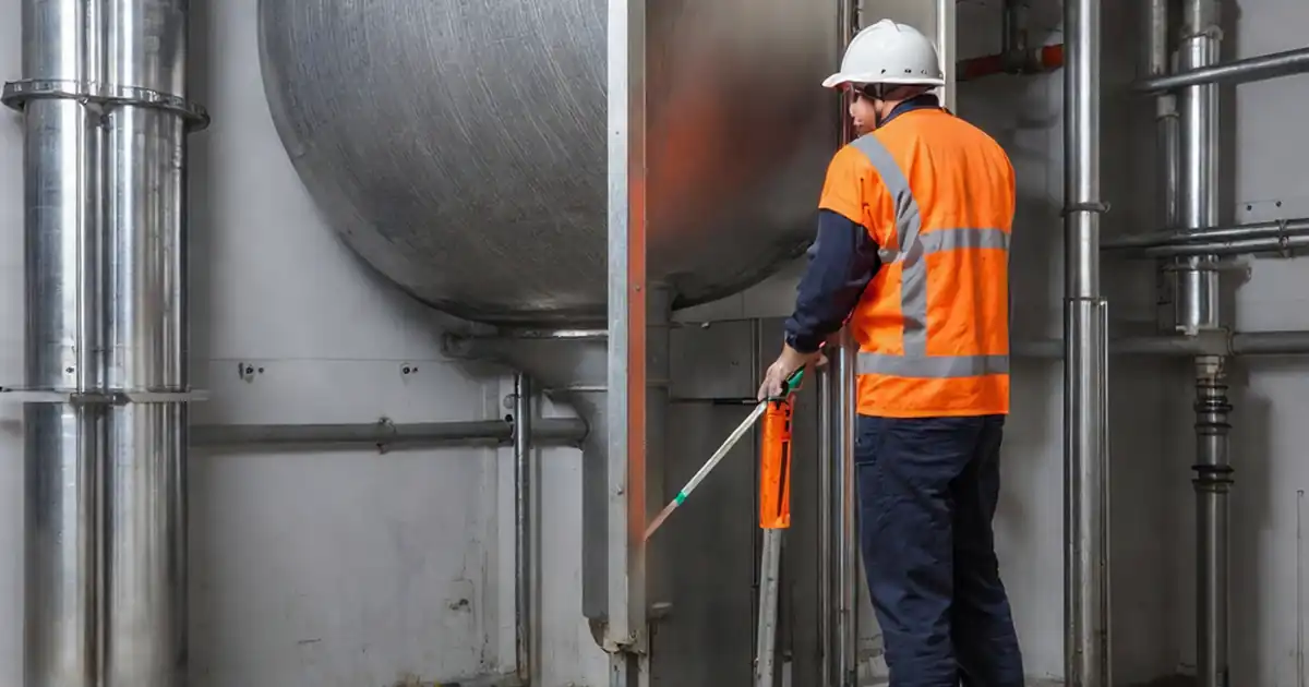
A rectangular duct transition inspection checks an equipment connection for dimensional accuracy, correct offset geometry, visible joint integrity, and a clear airflow passage against approved project references.
- Use approved drawings, equipment connection requirements, and documented acceptance criteria.
- Compare opening dimensions, transition length, offsets, and orientation with the specified geometry.
- Inspect visible seams, connections, supports, and accessible interior areas.
- Record inaccessible areas as unverified and required leakage testing as outstanding until documented.
The checklist
Identify the Transition
- Confirm the transition location and connected equipment identifier against equipment tags or installation drawings.
Confirm Inspection References
- Obtain the applicable approved drawings, equipment connection requirements, and documented dimensional acceptance criteria. Record missing or conflicting information as unresolved rather than assigning an acceptance tolerance.
Confirm Equipment Isolation
- Before opening access or reaching into the duct, confirm that required equipment isolation has been completed under site procedures. Do not proceed with internal access if isolation cannot be confirmed.
Equipment-End Dimensions
- Measure and record the equipment-end opening width and height. Compare them with the specified connection dimensions using the same measurement basis as the reference detail.
Duct-End Dimensions
- Measure and record the duct-end opening width and height. Compare them with the approved drawing using the same measurement basis as the reference detail.
Transition Length
- Measure and record the transition's end-to-end length between the reference planes shown on the approved drawing, and compare it with the specified length.
Horizontal Offset
- Measure and record the horizontal offset between the two end-opening centerlines, and compare it with the approved drawing.
Vertical Offset
- Measure and record the vertical offset between the two end-opening centerlines, and compare it with the approved drawing.
Installed Orientation
- Verify that the installed transition orientation matches the specified offset direction and equipment arrangement.
Transition Profile
- Check the transition profile for unintended steps, buckling, or wall deformation that departs from the approved geometry.
Fabricated Seams and Corners
- Inspect fabricated seams and corners for visible openings, splits, or incomplete closure.
End-Connection Joint Types
- Verify that each end connection uses the joint type specified in its approved connection detail.
Connection Hardware
- Check connection fasteners or cleats for missing, loose, or improperly seated components against the approved connection detail.
Joint Seals
- Inspect seals required by the connection details for visible gaps, displaced gaskets, or discontinuous sealant.
Equipment Connection Alignment
- Check the equipment connection for visible evidence of forced alignment, flange distortion, or strain.
Transition Supports
- Verify that installed transition supports match the approved support arrangement.
Interior Foreign Objects
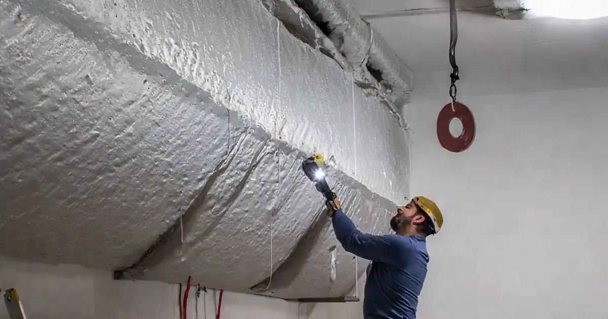
- Using available inspection access after required isolation is confirmed, inspect the transition interior for debris, packaging, tools, or other foreign objects.
Interior Obstructions
- Inspect the interior for loose liner, projecting joint material, or unintended component intrusions that reduce the specified clear airflow passage.
Inspection Coverage
- Record any surfaces, joints, or interior areas that could not be inspected. Mark the affected checks as unverified rather than passed.
Specified Leakage Testing
- Check whether the project documents require leakage testing applicable to this transition. If required, record the test report reference or mark testing as outstanding; do not substitute visual inspection for the test.
Restore Inspection Access
- For each access cover opened during inspection, verify that its seal is correctly seated and the cover is secured according to its installation requirements.
Record Results and Outstanding Work
- Record measurements, comparison results, visible defects, and unresolved checks against the transition identifier. Identify required corrections or clarification before marking affected checks complete.
Preview the printable checklist
Preview page one below. Open the image or download the PDF for all pages.

At a glance
- Identify the transition and establish the applicable inspection references before judging acceptance.
- Use the reference drawing’s measurement basis and reference planes for dimensional comparisons.
- Confirm required equipment isolation before opening access or reaching into the duct.
- Distinguish verified findings from unresolved information, inaccessible areas, and outstanding tests.
How to use the rectangular duct transition inspection checklist
- Establish the transition identifier and applicable approved references. Resolve missing or conflicting requirements rather than assuming acceptance criteria.
- Use the approved checklist to guide dimensional, geometry, connection, support, and accessible interior checks. Confirm required isolation before opening access or reaching inside.
- Record actual measurements and comparison results, keeping visible defects separate from checks that could not be verified.
- Document applicable leakage-testing status, verify restoration of opened access covers, and identify corrections or clarification needed before affected checks are completed.
Approved references define acceptance
Inspection findings depend on the correct equipment identifier, approved drawings, connection requirements, and documented dimensional acceptance criteria. Missing or conflicting information leaves the affected comparison unresolved; it does not justify assigning a field tolerance.
- Keep measurements and findings associated with the specific transition identifier.
- Compare dimensions using the same measurement basis as the reference detail.
- Seek clarification before completing checks that depend on unresolved requirements.
Geometry includes more than opening size
Equipment-end and duct-end dimensions are only part of the fit assessment. Transition length, horizontal and vertical centerline offsets, installed orientation, and wall profile establish whether the installed piece matches the approved geometry.
- Use the specified reference planes when comparing transition length.
- Assess offset direction as well as offset magnitude.
- Note unintended steps, buckling, deformation, or visible forced alignment.
Visible joint condition is not proof of airtightness
Seams, corners, end-joint types, hardware, and required seals provide evidence of installation condition. However, a visual inspection cannot establish airtightness or replace leakage testing required by the project documents.
- Assess connection details and supports against their approved arrangements.
- Document visible openings, incomplete closure, displaced seals, or connection distortion.
- Reference the applicable leakage test report or record required testing as outstanding.
Access limits must remain visible in the record
Interior inspection is limited to available access after required isolation has been confirmed under site procedures. Debris, loose liner, projecting joint material, and unintended intrusions can reduce the specified clear airflow passage. Areas that cannot be inspected remain unverified.
- Do not proceed with internal access if required isolation cannot be confirmed.
- Identify the surfaces, joints, and interior areas not inspected.
- Verify correct seal seating and secure closure for each access cover opened during inspection.