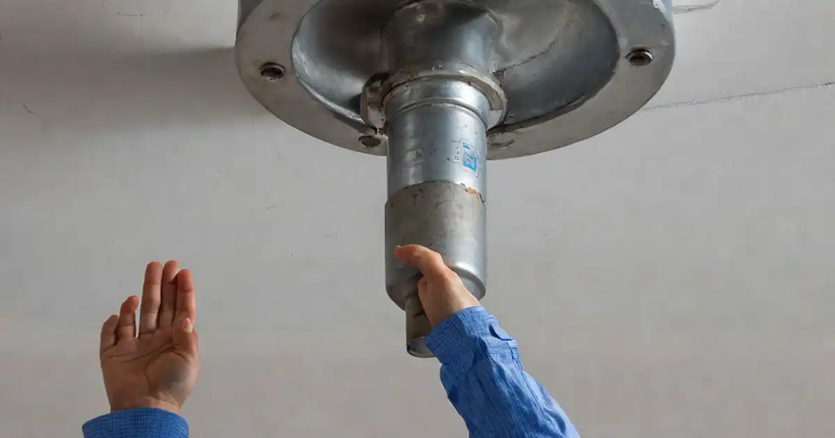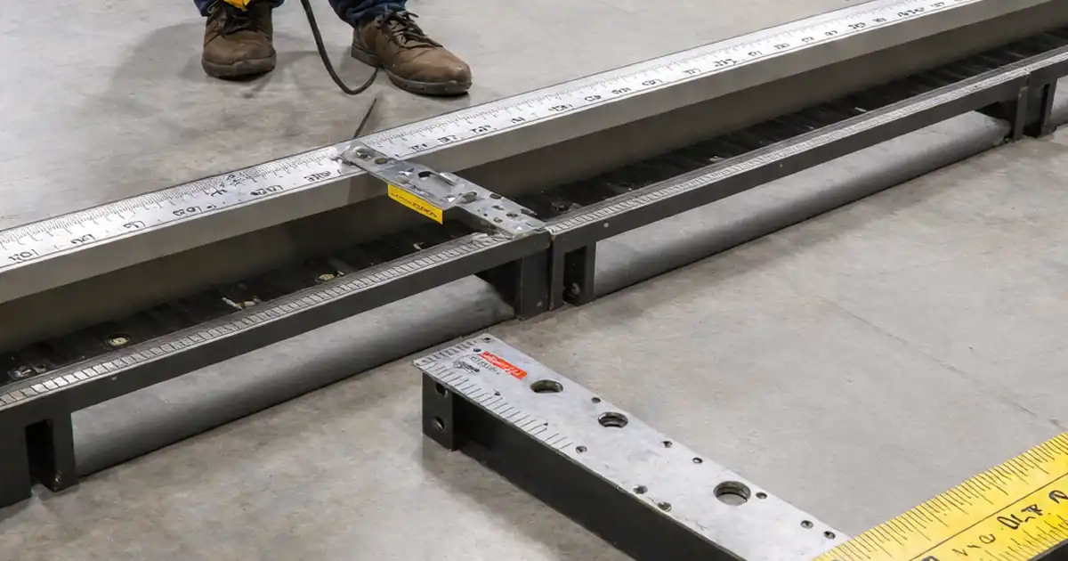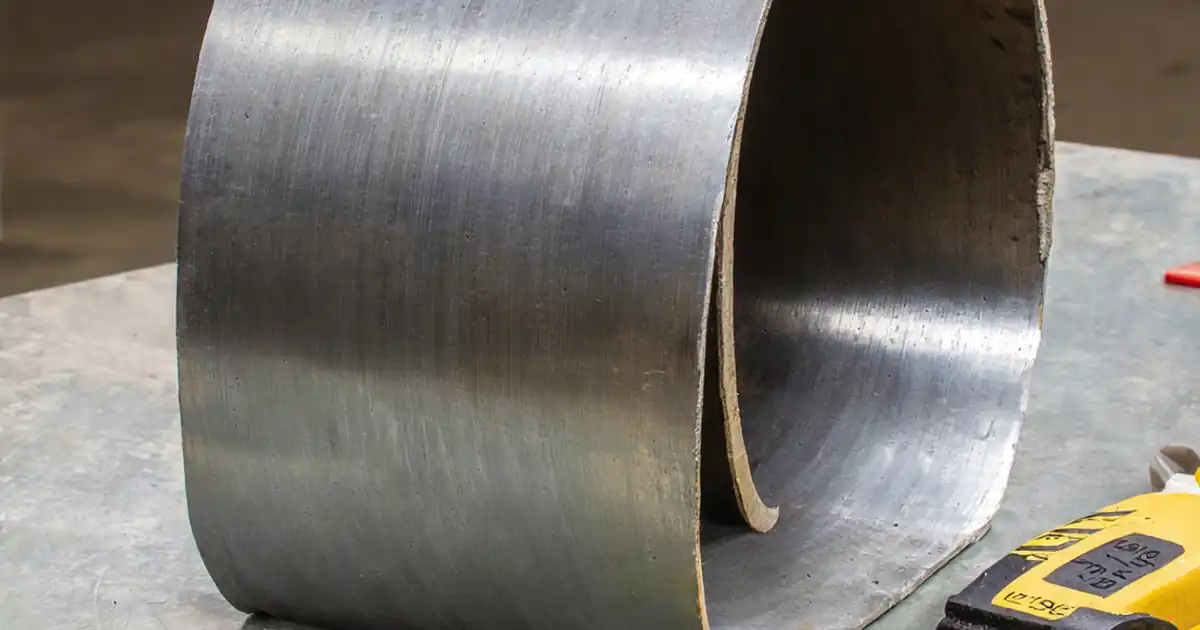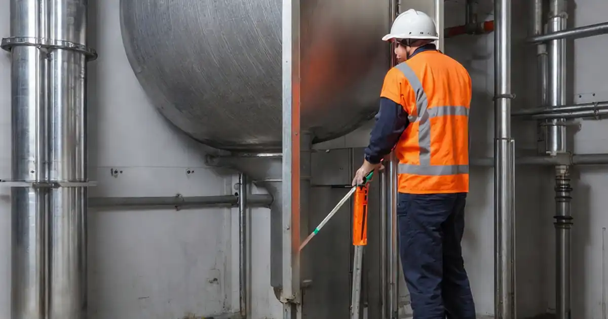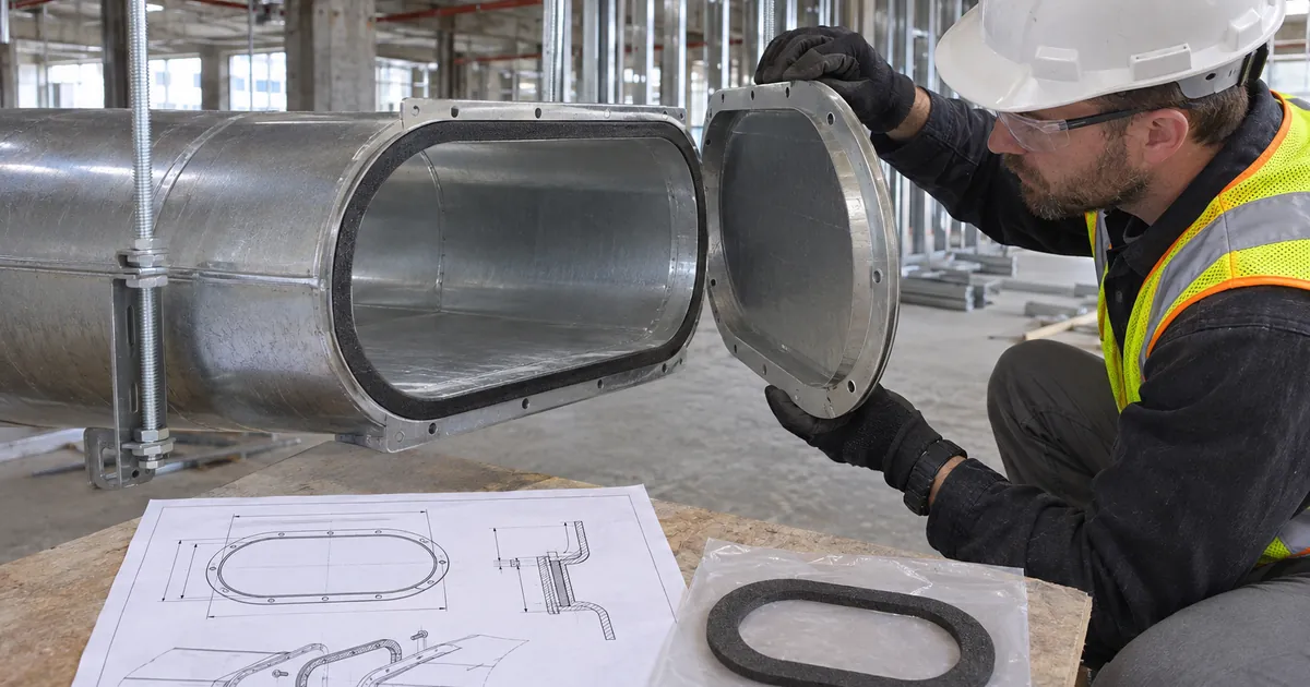
Flat-oval duct joint assembly inspection verifies mating flange geometry, gasket continuity, fastening, and duct alignment against applicable approved details and manufacturer installation instructions.
- Use the acceptance criteria for the installed joint system.
- Inspect concealed features before closure or review documented pre-closure evidence for the joint.
- Check the full perimeter, including straight sections and curved ends.
- Keep unverified features and unresolved discrepancies open rather than accepting them.
The checklist
Applicable Documents
- Confirm the applicable approved joint detail and manufacturer installation instructions are available and identify the joint being inspected.
Acceptance Criteria
- Confirm the referenced documents provide criteria for the installed joint system. Record missing or conflicting criteria for resolution before accepting the affected feature.
Concealed-Feature Evidence
- Confirm flange attachment, gasket surfaces, sealing path, splices, and seating can be inspected before closure or are supported by documented pre-closure inspection evidence for this joint. Record unsupported concealed features as unverified.
Flange System
- Verify the installed flange system matches the joint type specified in the approved detail.
Flange Profile and Dimensions
- Check each mating flange profile against the approved flat-oval dimensions and shape, including straight sections and curved ends.
Flange Face Condition
- Inspect mating flange faces for distortion or damage that would prevent the specified fit or uniform gasket contact.
Flange Attachment
- Verify flange attachment to each duct section matches the approved detail.
Gasket Material and Dimensions
- Verify gasket material and dimensions match the approved joint requirements.
Gasket Contact Surfaces
- Inspect gasket contact surfaces for debris or contamination before joint closure and verify surface preparation follows the applicable installation instructions.
Gasket Continuity
- Check that the gasket follows the specified sealing path continuously around both straight sections and curved ends.
Gasket Splices
- Verify each gasket splice follows the applicable approved or manufacturer-specified splice detail. Mark not applicable if there are no splices.
Gasket Seating
- Inspect the gasket before joint closure for damage, twists, folds, or displacement that would interrupt the specified seal.
Rotational Alignment
- Check rotational alignment of the mating flat-oval profiles against the approved detail.
Offset and Angular Alignment
- Verify offset and angular alignment between mating duct sections meet the applicable approved requirements.
Fastening Feature Registration
- Verify flange holes or other fastening features register without deformation inconsistent with the approved detail or installation instructions.
Fastener and Hardware Selection
- Verify installed fasteners and joint hardware match the approved type and size.
Fastening Locations and Spacing
- Check that all required fasteners and joint hardware are installed at the specified locations and spacing around the full perimeter.
Fastener Tightening
- Verify fastener tightening follows the manufacturer-specified method and sequence, including torque where specified, using observed installation or documented installation evidence.
Final Closure and Compression
- Verify final flange closure and gasket compression against the approved detail or manufacturer instructions using the specified inspection method.
Visible Gasket Condition
- Inspect the closed joint perimeter for visible gasket damage, extrusion, or displacement. Evaluate any observed condition against the applicable joint requirements rather than treating all visible extrusion as a defect.
Final Duct Alignment
- Verify rotational alignment, offset, and angular alignment remain within the applicable approved requirements after fastening.
Inspection Record
- Record the joint location, referenced document revisions, inspection findings, and any features that could not be verified.
Discrepancy Closeout
- Record discrepancies and their disposition. Verify corrections by reinspection and document the results before marking affected checks accepted; retain unresolved items as open.
Preview the printable checklist
Preview page one below. Open the image or download the PDF for all pages.

At a glance
- Approved joint details and manufacturer instructions establish the inspection criteria.
- Flange attachment, gasket contact surfaces, sealing path, splices, and seating require pre-closure access or documented evidence.
- Fastening and final closure must be evaluated using the applicable methods and requirements.
- Final alignment and discrepancy closeout remain part of acceptance after fastening.
How to Use the Flat-Oval Duct Joint Inspection Checklist
- Identify the joint and gather its applicable approved detail and manufacturer instructions. Resolve missing or conflicting acceptance criteria before accepting affected features.
- Coordinate inspection while concealed features remain accessible. If the joint is already closed, review documented pre-closure evidence and identify any unsupported features as unverified.
- Apply the approved checklist during assembly to evaluate flange geometry, gasket installation, alignment, and fastening against the referenced requirements.
- Complete the final assessment of closure, compression, visible gasket condition, and post-fastening alignment using the applicable inspection criteria.
- Record findings and discrepancies, verify corrections by reinspection, and retain unresolved items as open.
Use joint-specific acceptance criteria
The inspection depends on documents that apply to the installed flange and gasket system. Generic assumptions about dimensions, hardware spacing, tightening torque, or permissible misalignment do not replace the referenced requirements. Missing or conflicting criteria must be resolved before accepting the affected feature.
- Identify the joint and the applicable document revisions.
- Use the approved detail to evaluate flange type, profile, dimensions, and attachment.
- Refer unresolved criteria for resolution rather than supplying an assumed limit.
Plan for concealed-feature verification
Closure can hide conditions that are essential to evaluating the seal. A completed joint's exterior appearance does not establish that gasket surfaces were prepared correctly or that the gasket was continuous and properly seated before assembly. Where direct inspection is no longer possible, documented pre-closure evidence must support verification for that joint.
- Address flange attachment, contact surfaces, sealing path, splices, and seating before they are concealed.
- Evaluate gasket continuity through the straight sections and curved ends.
- Record unsupported concealed features as unverified.
Assess fastening and alignment together
Mating flat-oval profiles must meet the applicable rotational, offset, and angular alignment requirements. Fastening-feature registration, hardware selection, perimeter spacing, and tightening evidence help establish whether assembly followed the approved system. Alignment must also be verified after fastening.
- Evaluate registration without accepting deformation inconsistent with the installation requirements.
- Use the specified tightening method and sequence, including torque only where specified.
- Assess final closure and gasket compression using the specified inspection method.
Separate observations from acceptance decisions
Visible gasket extrusion is an observation to evaluate, not an automatic defect. Compare damage, extrusion, or displacement with the applicable joint requirements. Inspection records should distinguish accepted features from discrepancies, unavailable evidence, and conditions awaiting resolution.
- Record the joint location, document revisions, findings, and unverifiable features.
- Document discrepancy disposition and reinspection results.
- Keep affected checks open until corrections and verification support acceptance.