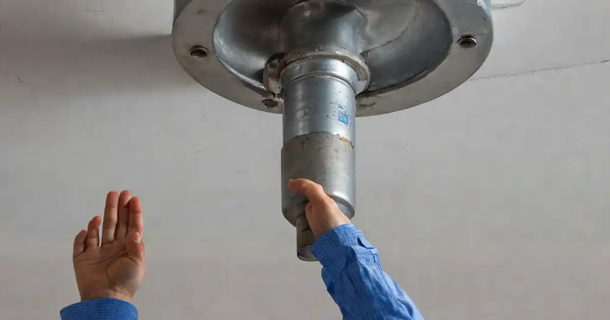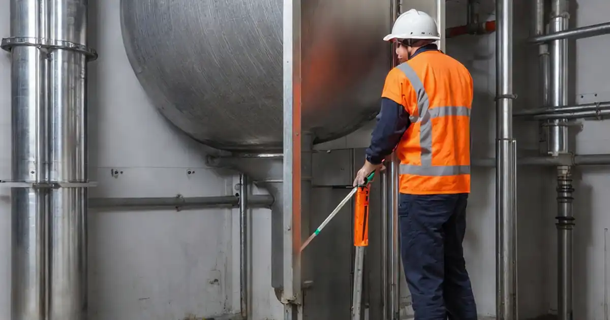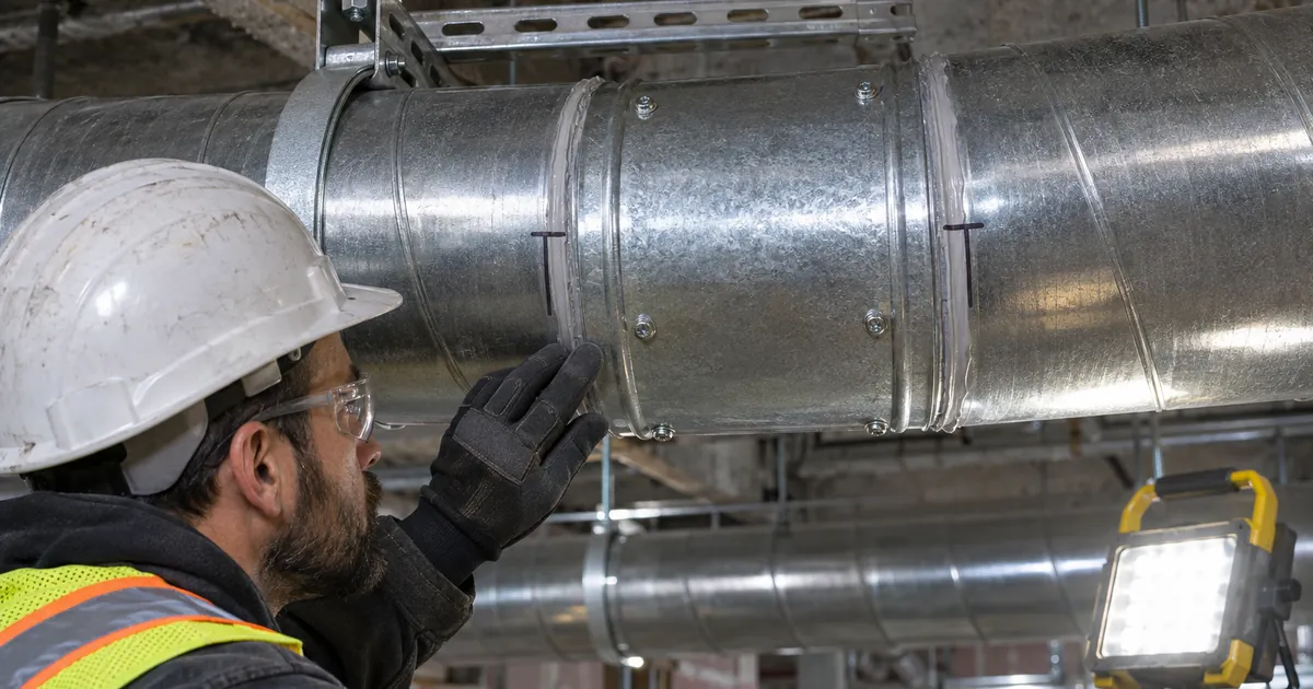
Circular duct coupling and slip-joint inspection verifies that each connection meets the applicable project detail and manufacturer’s instructions for engagement, fastening, sealing, and alignment.
- Verify engagement at every interface, including both ends of a coupling.
- Assess fasteners and sealing against the specified joint system, not assumed installation rules.
- Use joint-specific inspection evidence for concealed features.
- Keep checks unresolved when requirements or verification evidence are missing.
The checklist
Installation requirements
- Confirm the applicable project joint detail and manufacturer’s instructions establish engagement depth, fastening method, and sealing requirements. Resolve missing or conflicting requirements before accepting the joint.
Component condition
- Inspect the coupling and duct ends for deformation, burrs, or damage that would prevent proper seating or sealing.
Component compatibility
- Verify the coupling size, duct ends, and joint type are compatible with one another and with the specified sealing system.
Joint preparation
- Before assembly, verify mating surfaces meet the sealing-system instructions for cleanliness, dryness, and surface preparation. For assembled joints, review inspection evidence identifying the joint.
Engagement depth
- Verify specified engagement at every joint interface, including both ends of a coupling, using insertion marks, the specified seating stop, or documented measurements taken before concealment.
Circumferential engagement
- Check seating indicators around the full circumference of each interface for uneven insertion or partial withdrawal. Verify any variation remains within the applicable joint requirements.
Alignment
- Verify connected duct sections follow the intended alignment without unintended angular offset, forced fit, or joint distortion.
Duct support
- Verify nearby supports carry the duct without pulling the joint out of alignment or reducing the required engagement.
Fastener arrangement
- At each interface, compare fastener type, quantity, circumferential spacing, and edge distance with the applicable joint requirements. Verify compliance with any restrictions on penetrating gasketed connections. If no fasteners are specified, verify none have been added contrary to the instructions.
Fastener seating
- Inspect each required fastener for seating and tightening consistent with the installation instructions, without stripped holes or duct deformation that compromises the connection.
Gasket condition and seating
- For gasketed joints, verify each specified gasket is continuous, undamaged, and seated in its intended location without twists, displacement, or pinching. Use preassembly and assembly inspection evidence for concealed features.
Sealant continuity
- For sealant-based joints, verify continuous coverage around every interface at the specified sealing locations, including fastener penetrations where required. Check application dimensions against product instructions and use preassembly inspection evidence for concealed sealant.
Sealant readiness
- Verify the sealant has met the manufacturer’s applicable drying or curing requirements under the recorded application conditions before leakage testing or operation.
Leakage verification
- Where project requirements call for leakage testing, verify the joint lies within the documented test boundary and that the test results meet the specified acceptance criteria.
Defect closeout
- Verify recorded engagement, fastening, sealing, and alignment defects have been corrected and rechecked before insulation or other coverings conceal the joint. Confirm any required retesting is complete.
Preview the printable checklist
Preview page one below. Open the image or download the PDF for all pages.

At a glance
- The project joint detail and manufacturer’s instructions establish acceptance requirements.
- Engagement, alignment, and nearby supports must be considered together.
- Fastening and sealing checks depend on the specified connection system.
- Concealed work needs identifiable inspection evidence, and defects require verified closeout.
How to use the circular duct joint inspection checklist
- Establish the inspection basis using the applicable project joint detail and manufacturer’s instructions. Resolve gaps or conflicts before accepting affected checks.
- Identify the joint and gather available preassembly and assembly evidence so concealed conditions can be evaluated against the correct connection.
- Apply the approved checklist at each interface, using the specified joint system to determine which fastening, gasket, sealant, and testing checks apply.
- Record findings without treating missing evidence as a pass. Support any not-applicable decision with the specified system requirements.
- Verify corrections, rechecks, and any required retesting before the joint is concealed.
Use the specified joint system as the acceptance basis
There is no single engagement depth, fastener pattern, or sealing arrangement established by this checklist. Acceptance depends on the applicable project detail and manufacturer’s instructions. Missing or conflicting information must be resolved rather than replaced with an assumed rule.
- Confirm that the components and sealing system are compatible.
- Distinguish requirements that apply to all interfaces from those conditional on the joint type.
- Mark a conditional check not applicable only when the specified system supports that decision.
Evaluate engagement together with alignment and support
A coupling has separate interfaces that each need verification. Insertion marks, specified seating stops, or documented measurements can establish engagement, while circumferential seating indicators help reveal uneven insertion. Alignment and nearby supports also matter because a joint can be pulled out of position after initial assembly.
- Evidence from one coupling end does not establish engagement at the other.
- An apparently aligned duct run does not by itself prove sufficient insertion.
- Forced fit, joint distortion, and support-related movement need assessment against the applicable requirements.
Match fastening and sealing checks to the connection
Fasteners, gaskets, and sealants must be assessed as parts of the specified joint system. Added fasteners are not automatically an improvement, particularly where instructions restrict penetration of gasketed connections. Likewise, visible sealant on the exterior does not establish correct coverage at concealed sealing locations.
- Compare the fastener arrangement and seating with the applicable instructions.
- Use assembly evidence to assess concealed gasket condition and sealant coverage.
- Establish sealant readiness from the manufacturer’s drying or curing requirements and recorded application conditions.
Separate visual findings from evidence-based acceptance
For an assembled joint, some preparation, engagement, and sealing features may no longer be visible. Inspection evidence must identify the joint being evaluated. Where leakage testing is required, the documented boundary and results provide additional acceptance evidence but do not replace the other applicable checklist checks.
- Unavailable evidence leaves the affected check unresolved.
- Close out and recheck defects before insulation or other coverings conceal the connection.
- Confirm any required retesting is complete before acceptance.