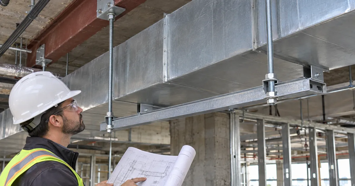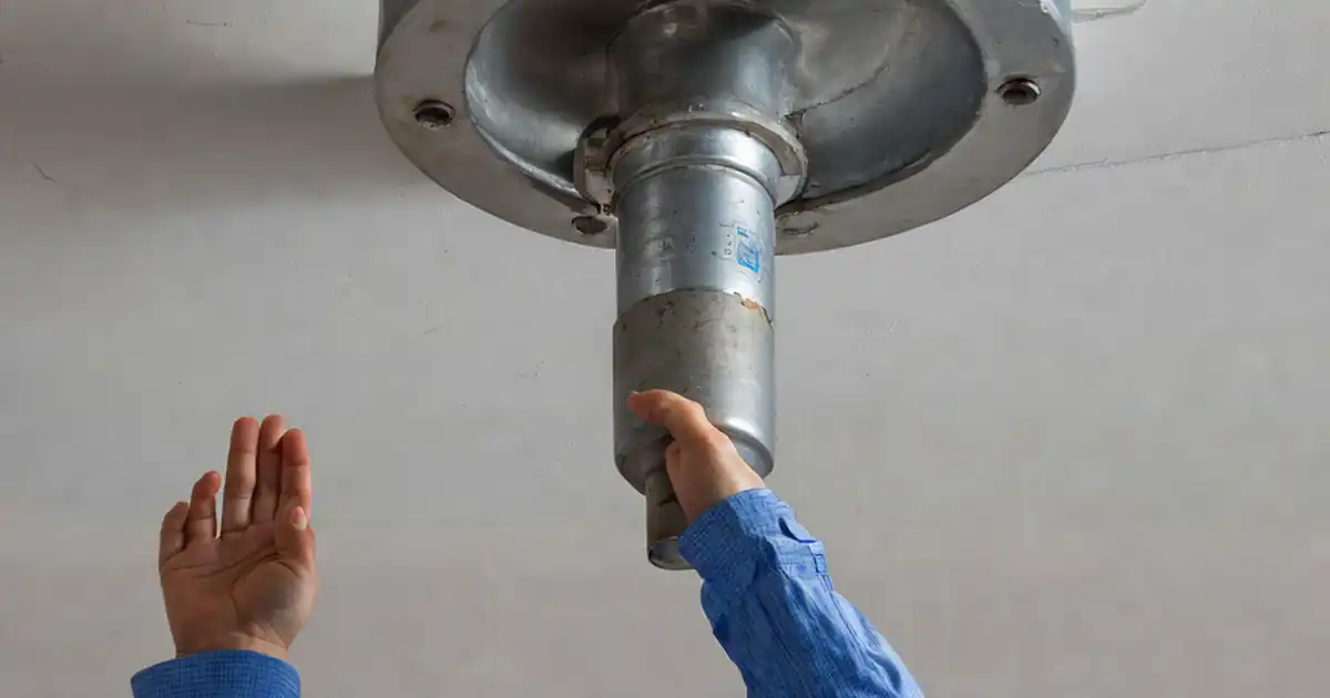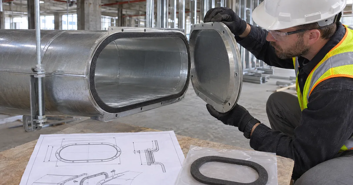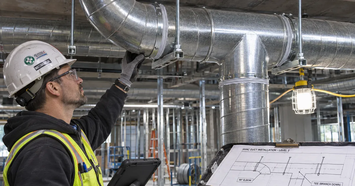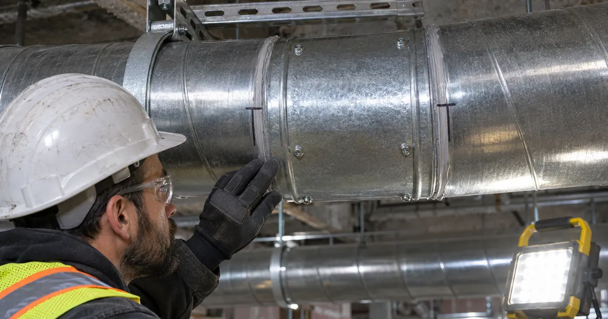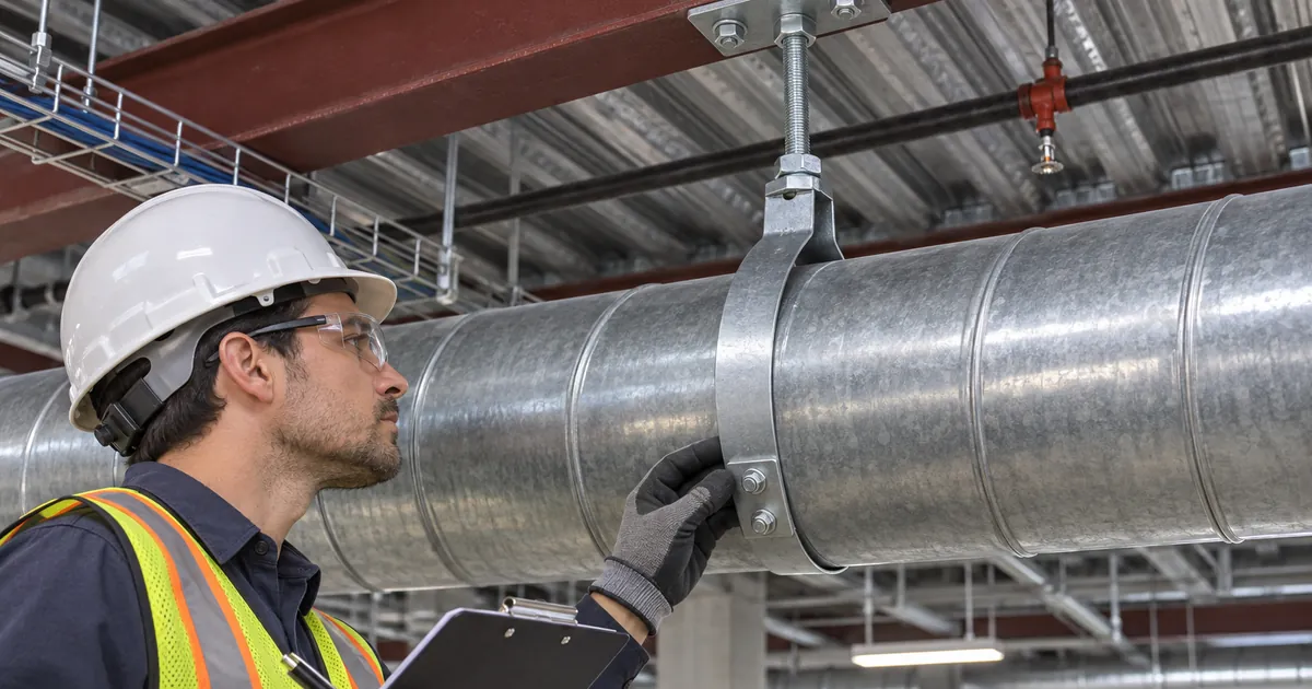
Horizontal circular duct band-hanger inspection checks whether installed bands, attachments and support locations match approved project details while protecting the duct from local deformation.
- Use approved details and applicable manufacturer instructions as the acceptance basis.
- Compare band dimensions, fastenings and support spacing with project requirements.
- Inspect bearing contact, duct shape and specified load-spreading components.
- Record results by hanger or duct-run location and resolve uncertainties before acceptance.
The checklist
Inspection Basis
- Confirm approved hanger details cover the installed duct diameter, material, supported load and support spacing. If criteria are missing or conflicting, record the affected locations and obtain clarification from the responsible designer before acceptance.
Band Material
- Verify band material matches the approved hanger specification using identification or traceable material documentation.
Band Width
- Measure band width and compare it with the approved requirement for the installed duct.
Band Thickness
- Verify band thickness against the approved requirement using a suitable measurement at an accessible edge or traceable material documentation.
Band Condition
- Inspect bands for cracks, tears, corrosion or unintended bends. Record any damage for evaluation against the approved requirements before acceptance.
Overhead Support Location
- Verify each overhead attachment connects to the structural member or support assembly identified in the approved detail.
Anchor Selection
- Compare anchor type, size and quantity with the approved attachment detail and verify compatibility with the actual substrate using the specified anchor manufacturer's instructions.
Anchor Installation
- Verify applicable anchor installation requirements, including embedment, edge distances and anchor spacing, against the approved detail and manufacturer's instructions. Use installation records for concealed features; record unverifiable requirements as unresolved.
Band-End Connections
- Compare band-end connection hardware, fastener quantity and connection arrangement with the approved hanger detail.
Connection Tightness
- Verify connection tightness using the specified inspection method. Do not apply an assumed torque; obtain clarification if the required verification method is unavailable.
Hanger-to-Hanger Spacing
- Measure and record hanger-to-hanger spacing along each duct run using the reference points defined by the approved detail, and compare each interval with the permitted spacing.
Supports at Ends and Joints
- Where the approved details specify support locations relative to duct ends or joints, measure the installed offsets and compare them with those requirements.
Fitting and Component Supports
- Verify support locations at fittings, branches and inline components against the approved details and applicable component manufacturer's support instructions.
Band Wrap and Bearing
- Verify band wrap and bearing contact match the approved detail, without unintended concentrated contact at band edges or connections.
Local Duct Deformation
- Inspect the duct at each band for visible denting, flattening, creasing or ovalization. Record affected locations and obtain evaluation against the approved criteria before accepting deformed ductwork.
Load-Spreading Components
- Where specified, verify saddles, liners or load-spreading inserts are present and match the approved material, dimensions and placement.
Insulated Duct Supports
- Where bands support insulated ductwork, verify the installed support arrangement matches the specified insulation-support detail and inspect for visible crushing at each support.
Preview the printable checklist
Preview page one below. Open the image or download the PDF for all pages.

At a glance
- Confirm the approved hanger detail applies to the installed duct diameter, material, load and support spacing.
- Use measurements, material documentation and installation records to support inspection findings.
- Assess the complete support arrangement, including attachments, connections and locations near components.
- Treat visible deformation and unverifiable requirements as matters requiring resolution before acceptance.
How to use the approved band-hanger inspection checklist
- Establish the inspection basis using approved hanger details and applicable manufacturer instructions. Resolve missing or conflicting criteria with the responsible designer before acceptance.
- Work through the approved checklist at each relevant hanger or duct-run location, using measurements, visual observations and traceable records as appropriate.
- Record actual findings against the applicable requirements, including support intervals and any damage, deformation or unverifiable concealed features.
- Obtain clarification or evaluation for unresolved findings and use the approved criteria to determine acceptance.
Project details establish the inspection basis
A hanger cannot be accepted solely because its appearance resembles a typical installation. The approved details must cover the actual duct and support arrangement. Missing or conflicting criteria need clarification from the responsible designer rather than an assumed field requirement.
- Relate findings to the applicable approved detail.
- Identify affected locations when criteria are incomplete or conflicting.
- Do not infer allowable dimensions, loads or spacing.
Material and connection evidence serve different purposes
Band identification and traceable material documentation help establish material and thickness, while accessible measurements establish installed dimensions. Attachment and connection checks address how the assembly transfers load to the designated overhead support. Concealed anchor features require installation records; appearance alone does not verify them.
- Keep material verification distinct from condition assessment.
- Use the specified anchor manufacturer's instructions with the approved attachment detail.
- Verify tightness by the specified method, not an assumed torque.
Support spacing depends on location as well as distance
Hanger-to-hanger intervals are only one part of support layout. Approved details may also define offsets at duct ends and joints, while fittings, branches and inline components may have specific support arrangements. Measurements must use the reference points defined by the approved detail to make comparisons meaningful.
- Record individual intervals along each duct run.
- Assess end and joint offsets where specified.
- Consider applicable component manufacturer's support instructions.
Bearing contact is central to duct protection
A band may match its specified dimensions yet still bear improperly against the duct. Inspection should distinguish the intended wrap and bearing arrangement from unintended concentrated contact at edges or connections. Visible dents, flattening, creases or ovalization require evaluation against approved criteria before acceptance.
- Evaluate duct condition at each band location.
- Check specified saddles, liners and inserts against their approved arrangement.
- For insulated ductwork, assess the specified insulation-support detail and visible crushing.
Location-based records support clear closeout
Recording results by hanger or duct-run location connects each measurement, document reference and unresolved finding to the installed work. This makes it easier to distinguish verified conditions from those still awaiting evidence or design evaluation.
- Associate observations and measurements with identifiable locations.
- Record concealed requirements that cannot be verified as unresolved.
- Do not accept unresolved deviations or deformed ductwork without the required evaluation.