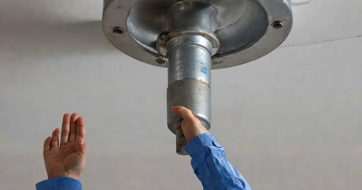
Inspection of duct support anchors in concrete verifies that the installed anchors, concrete conditions, and installation evidence match location-specific approved details and product-specific manufacturer instructions.
- Link observations, measurements, and records to each inspected support or anchor location.
- Verify anchor identity, geometry, effective embedment, and concrete edge distances.
- Use installation records to assess concealed conditions that cannot be verified visually.
- Resolve discrepancies through the responsible authority before release for use.
The checklist
Inspection Location and Traceability
- Record the inspected support and anchor locations so photographs, measurements, installation records, and test reports can be linked to the installation.
Approved Anchor Requirements
- Confirm the current approved support detail identifies the anchor product, diameter, quantity, embedment, spacing, and concrete edge distances applicable to the inspected location.
Product Installation Instructions
- Confirm the available manufacturer's installation instructions apply to the installed anchor product and size. Refer conflicts with the approved detail to the responsible design authority before acceptance.
Installed Anchor Product
- Verify the installed anchor product against the approved support detail using product markings and traceable installation or supply records.
Anchor Diameter
- Verify installed anchor diameter against the approved support detail using accessible measurements or traceable records.
Anchor Material and Finish
- Verify anchor material or protective finish matches the approved specification for the installation environment.
Concrete Application Suitability
- Verify documented concrete strength and the specified cracked or uncracked design condition are compatible with the approved anchor application. Do not classify concrete as uncracked solely from a visual inspection.
Concrete Member Thickness
- Verify concrete member thickness at the anchor location meets the approved detail and applicable manufacturer requirements using drawings, measurements, or traceable records.
Visible Concrete Condition
- Inspect concrete around each anchor for spalling, crushing, exposed reinforcement, or cracks. Record defects for disposition against the approved anchor application before acceptance.
Anchor Quantity
- Verify anchor quantity at each duct support against the approved support detail.
Anchor Spacing
- Measure anchor center-to-center spacing and compare it with the approved support detail and applicable manufacturer requirements.
Concrete Edge Distance
- Measure from each anchor centerline to relevant concrete edges, including nearby openings, and compare with the approved support detail and applicable manufacturer requirements.
Effective Embedment
- Verify effective embedment against the approved requirement using installation measurements or traceable records interpreted for the specific anchor product. Do not infer embedment solely from exposed thread length or drilled hole depth.
Drilling Method
- For drilled anchors, verify the recorded drilling method is permitted by the manufacturer's instructions for the installed product and concrete condition.
Hole Diameter and Depth
- For drilled anchors, verify recorded hole diameter and depth against the manufacturer's instructions and approved embedment requirement.
Hole Cleaning
- For drilled anchors, verify traceable installation evidence shows that hole cleaning followed the manufacturer's procedure for the drilling method used.
Exposed Hardware Condition
- Inspect exposed anchors, nuts, and washers for damage, corrosion, or unauthorized modification. Record suspect conditions for disposition before acceptance.
Bracket Seating
- Verify bracket seating against the approved detail, including any specified grout, shims, or stand-off arrangement.
Washers and Thread Engagement
- Verify washer arrangement and, where applicable, nut thread engagement against the approved detail and manufacturer's instructions.
Mechanical Anchor Setting
- For mechanical anchors, verify documented setting or tightening meets the product-specific procedure. Do not retorque or otherwise disturb an installed anchor unless the applicable procedure permits it.
Adhesive Identity and Shelf Life
- For adhesive anchors, verify traceable installation records identify the specified adhesive and show it was within its shelf life when installed.
Adhesive Orientation and Loading
- For adhesive anchors, verify the approved anchor system permits the installed orientation and applicable sustained loading condition.
Adhesive Installation Conditions
- For adhesive anchors, verify recorded hole moisture and installation temperatures were within the manufacturer's permitted conditions.
Adhesive Mixing and Dispensing
- For adhesive anchors, verify installation evidence documents compliance with the manufacturer's mixing and dispensing procedure, including specified equipment and initial adhesive discard where required.
Adhesive Placement and Anchor Insertion
- For adhesive anchors, verify installation evidence documents adhesive placement and anchor insertion in accordance with the manufacturer's procedure, including working time and insertion depth.
Adhesive Cure Before Loading
- For adhesive anchors, verify the manufacturer's required cure time for the recorded temperature and hole condition elapsed before tightening or loading.
Specified Inspection and Testing
- Verify inspections and tests required by the approved project inspection plan are complete, with results accepted by the designated authority and traceable to the inspected anchors. Do not apply an improvised proof load.
Discrepancy Resolution and Release
- Before release for use, verify missing evidence, damage, conflicting requirements, and deviations have documented disposition by the responsible design or inspection authority within its assigned role. Confirm required corrective work and reinspection are complete; otherwise record the support as not accepted.
Preview the printable checklist
Preview page one below. Open the image or download the PDF for all pages.

At a glance
- Use the current approved support detail together with instructions for the installed anchor product and size.
- Distinguish directly observable conditions from concealed conditions requiring installation evidence.
- Apply mechanical-anchor and adhesive-anchor checks only where relevant.
- Do not accept unresolved safety-critical conditions or perform improvised tightening or load testing.
How to Use the Duct Support Anchor Inspection Checklist
- Identify the support and anchor locations, then assemble the current approved details, applicable manufacturer instructions, and traceable installation records.
- Work through the approved checklist as issued, recording location-linked observations, measurements, and supporting evidence.
- Apply conditional checks according to the installed anchor type and installation method. Mark them not applicable only when those conditions make them irrelevant.
- Record missing evidence, damage, conflicts, and deviations for disposition by the responsible authority rather than assuming compliance.
- Close the inspection only after required dispositions, corrective work, reinspection, and accepted test results are documented. Otherwise record the support as not accepted.
Establish the inspection basis and traceability
The approved support detail establishes the requirements for each location. Manufacturer instructions provide the product-specific installation procedures. Inspection records need to connect both sources to the actual support and anchors so that evidence can support an acceptance decision.
- Use location identifiers to link photographs, measurements, supply records, installation records, and test reports.
- Verify product identity through markings and traceable records rather than appearance alone.
- Refer conflicts between approved details and manufacturer instructions to the responsible design authority before acceptance.
Interpret geometry and concrete condition correctly
Anchor spacing, edge distance, member thickness, and effective embedment must be evaluated against the applicable approved requirements. Visible concrete condition is important, but it does not establish every design assumption.
- Measure spacing center to center and edge distance from the anchor centerline to relevant concrete edges, including openings.
- Do not infer effective embedment solely from exposed thread length or drilled hole depth.
- Do not classify concrete as uncracked solely because no cracks are visible.
- Record concrete defects for disposition against the approved anchor application.
Use evidence for concealed installation conditions
A completed installation can conceal drilling, cleaning, setting, and adhesive-placement conditions. Traceable installation evidence is therefore essential where these conditions affect acceptance. The applicable evidence depends on the anchor product and installation method.
- For drilled anchors, review evidence of drilling method, hole dimensions, and hole cleaning.
- For mechanical anchors, verify documented setting or tightening without disturbing the anchor unless the applicable procedure permits it.
- For adhesive anchors, review product identity, shelf life, permitted orientation and loading, installation conditions, placement, and cure before loading.
Keep acceptance within the assigned authority
The checklist supports a documented inspection decision; it does not authorize redesign, improvised testing, or acceptance of unverifiable safety-critical conditions. Missing evidence and deviations require disposition by the responsible design or inspection authority within its assigned role.
- Confirm required project inspections and tests are complete and their accepted results are traceable to the anchors.
- Do not apply an improvised proof load.
- Confirm corrective work and reinspection are complete before release; otherwise record the support as not accepted.