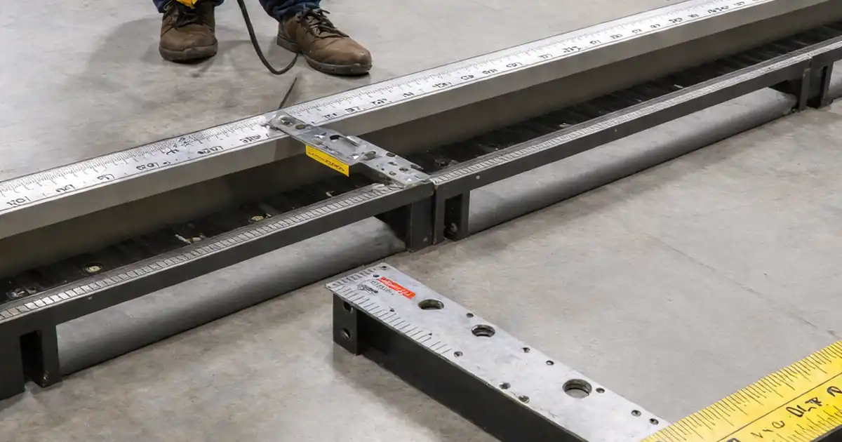
Inspect rectangular duct transverse flange assembly before installation for HVAC QA teams, verifying flange profiles, corner pieces, fasteners, and joint fit-up while excluding gasket sealing to reduce rework and ensure reliable assembly.
- Confirm flange profile, corner compatibility, and hardware before site installation
- Measure straightness, squareness, and fit-up to tight millimetre tolerances
- Dry-fit sections to verify hole alignment and even flange contact
- Interactive, commentable checklist with export and QR code verification
The checklist
Documentation & Identification
- Verify approved submittals for the specified transverse flange system against drawings; record document numbers and approval stamps; photograph data plates/labels for traceability.
- Confirm each duct section ID matches the schedule and tag; annotate the checklist with location/zone; capture a clear photo of the physical tag.
- Record batch/heat numbers for flange profiles and corner pieces from packaging; photograph labels; store numbers in the log for material traceability.
- Check calibration dates for tape, caliper, straightedge, feeler gauges, and torque wrench; accept only in‑date tools; attach calibration certificates as files.
Flange Profiles
- Confirm flange profile type and material match the approved cut sheet (e.g., TDC/TDF or angle frame); acceptance: exact model/material; photograph profile end.
- Measure flange leg and face dimensions with a caliper; tolerance: within ±1.0 mm of specification; record three readings per side and attach photos.
- Check straightness along each flange edge using a 1 m straightedge and feeler gauges; acceptance: gap ≤2 mm per 1 m; photograph gauge at largest gap.
- Verify flange face flatness across the frame using cross-edge straightedge; acceptance: local flatness deviation ≤1 mm; log max deviation and photo evidence.
- Inspect cut edges for burrs and sharpness; acceptance: no burrs >0.5 mm; perform glove sweep test; photograph any reworked edges.
Corner Pieces
- Confirm corner pieces match the flange system and material grade; check part numbers/stamps; acceptance: full compatibility; attach photo of markings.
- Check each corner is fully seated and flush with flange lips; acceptance: visible gap at seams ≤1 mm; verify with 1 mm feeler; capture corner close-ups.
- Verify mechanical retention (clinches/rivets/bolts) per specification; acceptance: required quantity present and tight; record counts per corner with photos.
- Measure frame squareness by comparing diagonal lengths of the flange rectangle; acceptance: Δdiagonals ≤3 mm up to 1 200 mm side, ≤5 mm above; record values.
Fasteners & Hardware
- Confirm fastener type/size/coating per specification (e.g., M6/M8, stainless/zinc); verify packaging labels; record lot numbers; photograph unopened boxes.
- Inspect threads and heads for damage or contamination; acceptance: no cross-threading, rust, or bent shanks; perform nut run by hand; attach defect photos.
- Check presence and orientation of washers/lock devices where required; acceptance: complete set per bolt; document counts and photograph sample assemblies.
- Verify torque on a sample test rig (not production joint): M6 = 6–10 N·m, M8 = 16–20 N·m; use calibrated torque wrench; record achieved values.
Joint Fit-Up & Geometry
- Dry-fit two mating duct sections on level supports; acceptance: uniform flange contact with overall gap ≤2 mm; no forced prying; photograph full perimeter.
- Check hole alignment at four corners using a gauge pin or bolt; acceptance: misalignment ≤1 mm; record locations and attach close-up photos.
- Measure panel step across the joint with a straightedge; acceptance: step ≤2 mm; log measurements on all sides; capture photos with ruler reference.
- Inspect gasket groove or flange sealing face only for cleanliness and damage (no gasket work); acceptance: free of dents, oil, and debris; photograph condition.
- Verify flange plane alignment using a level and cross-corner check; acceptance: out-of-plane offset ≤1.5 mm between mating faces; record readings.
Handling, Storage & Readiness
- Confirm storage is dry, clean, and elevated ≥100 mm off ground; acceptance: no standing water or floor contact; photograph storage setup.
- Check stacks use spacers at ≤1.0 m centers; acceptance: no flange bending or distortion; document stack height and spacer spacing with photos.
- Verify lifting uses soft slings away from flange edges; acceptance: no deformation or denting after lift; capture before/after photos.
- Label assembly as “Ready for Install – No Gasket” with date/initials; affix QR code to link the report; upload final photos.
Preview the printable checklist
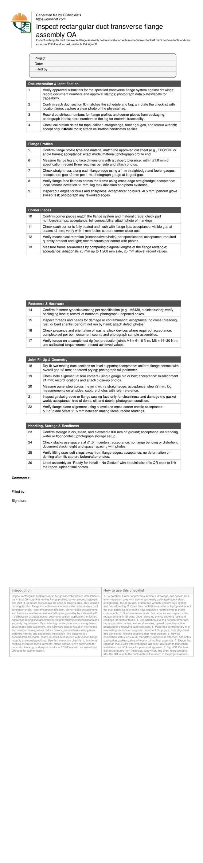
Preview page one below. Open the image or download the PDF for all pages.
At a glance
- Validate flange profiles, corner pieces, and fasteners against approved submittals, then dry-fit sections to confirm uniform contact, aligned holes, and correct geometry—reducing field adjustments, avoiding distortion, and enabling faster, cleaner installations.
- Apply practical tolerances with simple tools: straightedge and feeler gauges for 1–2 mm flatness/straightness, diagonal checks for squareness, and calibrated torque wrenches for fastener readiness—capturing photos and readings for traceability.
- Interactive online checklist with tick, comment, and export features secured by QR code.
- Document batch numbers, calibration dates, and inspector sign-offs to prove material traceability and measurement integrity, ensuring conformance per approved project specifications and authority requirements without addressing gasket sealing.
How to Use This Interactive Flange Assembly Inspection Checklist
- Preparation: Gather approved submittals, drawings, and specs; set a level inspection area with sawhorses; ready calibrated tape, caliper, straightedge, feeler gauges, and torque wrench; confirm safe lighting and housekeeping.
- Open the checklist on a tablet or laptop and select the duct batch/IDs to create a new inspection record linked to those components.
- Start interactive mode: tick items as you inspect; enter measurements in SI units; attach close-up photos showing tools and readings for each criterion.
- Use comments to flag nonconformances, tag responsible parties, and set due dates; upload corrective-action photos before resolving each comment.
- Perform a controlled dry-fit of two mating sections on supports; document fit-up gaps, hole alignment, and panel step; remove sections after measurement.
- Review completion status; ensure all mandatory evidence is attached; add notes stating that gasket sealing will occur during final assembly.
- Export the report as PDF/Excel with embedded QR code; distribute to fabrication, installation, and QA leads for pre-install approval.
- Sign-Off: Capture digital signatures from inspector, supervisor, and client representative; affix the QR label to the duct; archive the record in the project system.
Why pre-install transverse flange checks prevent costly rework
Rectangular duct joints succeed or fail at the flange. Pre-install inspection verifies that flange profiles match the approved system, corner pieces are fully seated, and fasteners are correct before crews mobilize. By confirming straightness, flatness, and squareness, you prevent distortion that otherwise forces installers to pry, over-torque, or misalign sections in the field. A brief dry-fit exposes hole misalignment and panel step so corrections happen in the shop, not on lifts. This checklist excludes gasket sealing and sealant application; those occur during final assembly per approved project specifications and authority requirements. Recording measurements, photos, and batch numbers builds traceability, protecting you during commissioning and warranty. The result is a consistent, low-leak joint foundation that speeds installation and reduces punch items, especially on large, multi-section rectangular runs where repetition amplifies small errors.
- Match flange system to approved submittals and drawings.
- Confirm corner seating and mechanical retention.
- Measure straightness, flatness, and squareness precisely.
- Dry-fit to reveal misalignment early.
- Exclude gasket work until final assembly.
Practical methods, tools, and acceptance cues in millimetres
Use calibrated basics: a 1 m straightedge with feeler gauges for straightness and flatness; a caliper for leg and face dimensions; a steel tape for diagonals; and a torque wrench for hardware validation on a test rig. Typical acceptances include straightness gaps ≤2 mm per 1 m and local flatness ≤1 mm at the flange face. For geometry, keep diagonal difference ≤3 mm up to 1 200 mm sides and ≤5 mm above. During dry-fit, target a uniform contact line with total perimeter gap ≤2 mm and panel step ≤2 mm. Hole alignment should be within 1 mm to avoid forced bolting later. Record all readings in SI units and attach photos with measurement tools visible. These cues provide objective, repeatable criteria that supervisors and auditors can trust on any shop floor or site.
- Use calibrated measuring tools only.
- Record SI units with photo evidence.
- Straightness gap limit: 2 mm per metre.
- Diagonal difference: 3–5 mm by size.
- Dry-fit gap target: ≤2 mm overall.
Documentation, traceability, and interactive collaboration
Quality evidence matters as much as the inspection itself. Capture submittal references, packaging labels, batch numbers, and calibration certificates to prove you used the right materials and tools. Photograph edges, corners, measurement setups, and dry-fit conditions from multiple angles. Use the interactive checklist to assign comments to specific items, tag responsible parties, and track resolutions before shipment. Export records to PDF/Excel with embedded QR code so field teams and auditors can instantly authenticate the latest version. This approach prevents disputes over torque values, corner counts, or straightness results and helps align fabricators, installers, and commissioning agents. With clear acceptance criteria and verifiable artifacts, each duct section leaves the shop marked “Ready for Install – No Gasket,” ensuring a smooth transition to site assembly and final sealing per approved project specifications and authority requirements.
- Log batches and calibration certificates.
- Attach photos with tools visible.
- Use comments to assign actions.
- Export with QR for authentication.
- Label sections ready for install.