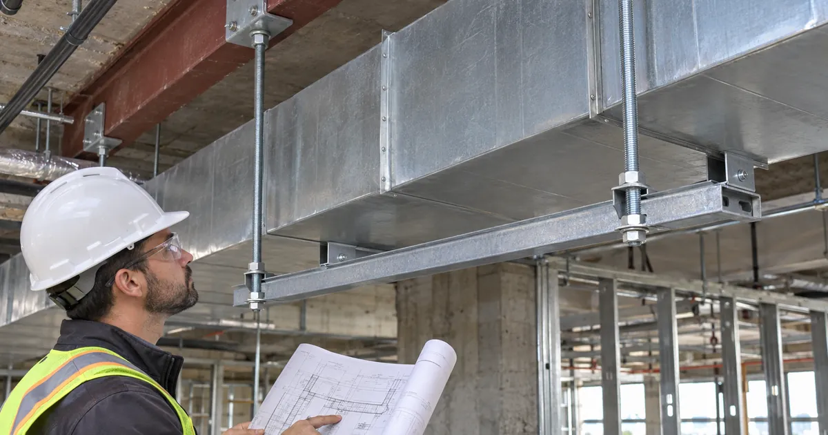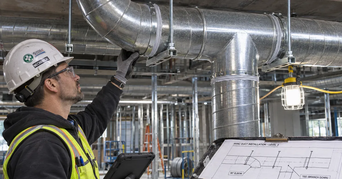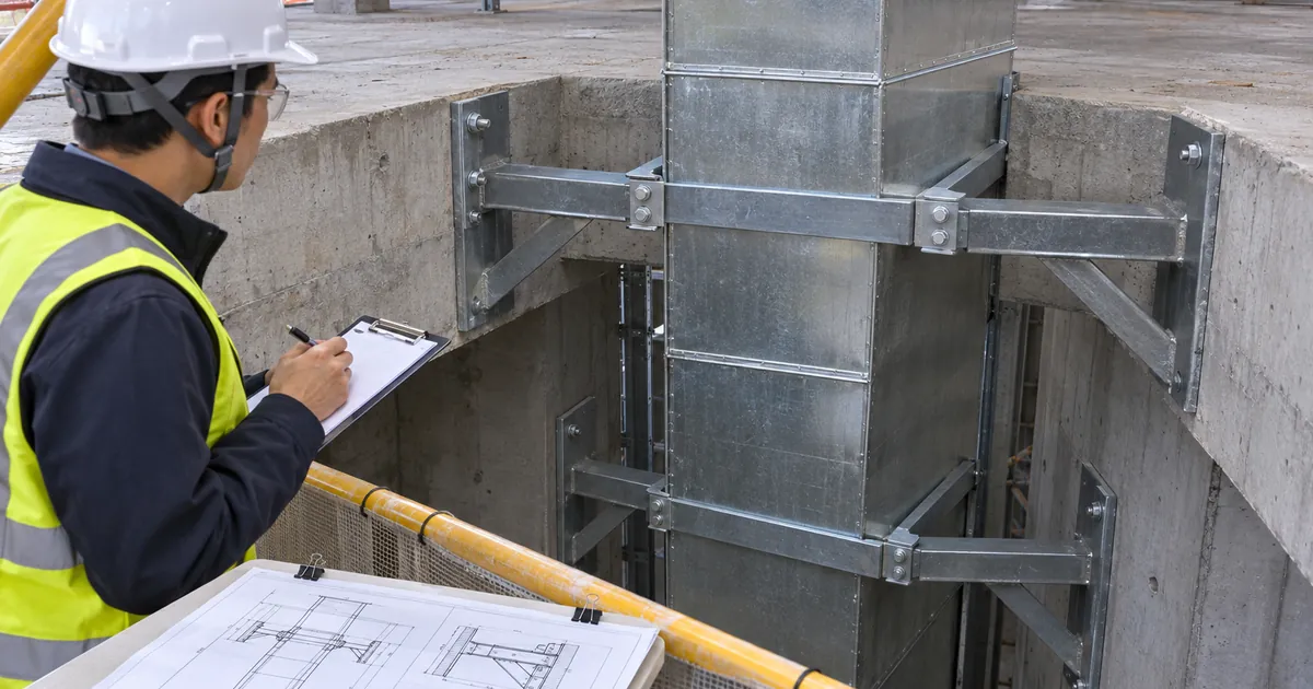
A vertical duct riser support inspection checks floor-level brackets, anchors, load-transfer interfaces and alignment against approved project details. It does not independently establish structural capacity.
- Use current approved support layouts, connection details, anchor requirements and alignment criteria.
- Combine accessible observations and measurements with suitable installation records.
- Do not disturb loaded supports or enter unprotected openings.
- Refer discrepancies and unresolved checks to the responsible engineer.
The checklist
Safe inspection access
- Confirm the inspection location is accessible without entering an unprotected opening or disturbing loaded supports. Do not proceed where safe access is unavailable.
Applicable inspection documents
- Identify the current approved support layout, connection details, anchor installation requirements and alignment criteria for the riser and floor being inspected. Record missing information as an unresolved check.
Floor support locations
- Verify that support locations at each inspected floor match the approved riser support layout.
Supporting structure and substrate
- Verify that the structural element and substrate receiving each support match those identified in the approved support and anchor details. Use project records for concealed characteristics.
Bracket specification
- Compare bracket sizes, materials and configuration with the approved support details, using identification or material records where visual inspection cannot establish the material.
Bracket condition
- Inspect brackets for visible bending, cracking, corrosion or modifications not shown in the approved details.
Duct connection and reinforcement
- Verify that bracket-to-duct connections match the approved details, including specified reinforcement.
Weld configuration and condition
- Compare accessible connection weld locations, lengths and measurable sizes with the approved details; record visible cracks or separation. Do not treat visual checks as proof of concealed weld quality.
Connection fastener arrangement
- Verify bracket connection bolt sizes, grades, nuts and washers against the approved details using markings or records as needed.
Connection bolt tightening
- Check records for any specified bracket connection bolt-tightening verification. Do not loosen or retighten loaded connections solely to perform this inspection.
Anchor specification and arrangement
- Verify anchor type, size, quantity and arrangement against the approved anchor details, using installation records where concealed.
Anchor spacing and edge distances
- Measure accessible anchor spacing and edge distances against the approved anchor details; use installation records for concealed dimensions.
Substrate condition around anchors
- Inspect the supporting substrate around anchors for visible cracking, spalling or deterioration.
Anchor assembly condition
- Inspect anchor assemblies for displacement, missing fastening components or gaps inconsistent with the approved details.
Anchor installation evidence
- Check installation records for specified embedment and applicable setting, curing and tightening verification against the approved anchor requirements.
Continuous load path
- Trace the installed load path from the duct through its connections and brackets to the designated structural element, comparing each interface with the approved details.
Bearing surfaces and packing
- Verify that bearing surfaces, shims and packers match the approved details without unintended gaps.
Duct condition at supports
- Inspect the duct at support contact points for local buckling, crushing or tearing.
Unintended bearing
- Check for unintended duct bearing on floor-opening edges, firestopping, adjacent services or finishes.
Riser plumb and position
- Measure and record riser plumb and position against the approved alignment criteria. Refer missing criteria for clarification rather than applying an assumed tolerance.
Bracket and bearing alignment
- Verify bracket orientation and bearing alignment against the approved support details.
Fixed and movement supports
- Verify that specified fixed, guided or sliding support arrangements match the approved details and have no visible obstruction to intended movement. Do not force movement of loaded supports.
Inspection evidence and limitations
- Record findings by floor and support identifier, including measurements, photographs and document references. Mark inaccessible checks as unverified unless suitable records establish conformity; identify genuinely inapplicable checks separately.
Discrepancy referral and acceptance
- Record referral of discrepancies, suspected instability, unresolved checks and missing design information to the responsible engineer. Keep affected supports pending acceptance until the required disposition or evidence is documented.
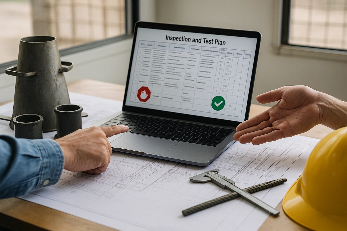
Preview the printable checklist
Preview page one below. Open the image or download the PDF for all pages.

At a glance
- Assess brackets, duct connections and anchors against the approved details for the inspected floor.
- Trace the load path through each interface and identify unintended bearing.
- Measure alignment against project criteria rather than assumed tolerances.
- Record findings by floor and support identifier, keeping unresolved supports pending acceptance.
How to use the approved inspection checklist
- Establish safe inspection access and gather the current approved documents for the riser and floor. Do not proceed where access requires entering an unprotected opening or disturbing loaded supports.
- Work through the approved checklist using accessible observations, measurements and suitable project records. Keep the checklist unchanged and assess findings against its referenced project details.
- Record results by floor and support identifier, with photographs, measurements, document references and clear limitations on what was verified.
- Refer discrepancies and unresolved information to the responsible engineer. Retain pending acceptance status for affected supports until the required evidence or disposition is documented.
Approved details provide the inspection baseline
The inspection depends on the current approved arrangement for the specific riser and floor. Support locations, receiving structure, bracket configuration and anchor requirements must be assessed against that information, not against a typical installation.
- Use project records where substrate characteristics, materials or installation dimensions are concealed.
- Treat missing design information as an unresolved check.
- Do not substitute assumed alignment tolerances for approved criteria.
Visible condition and installation evidence serve different purposes
Accessible surfaces can reveal deformation, cracking, corrosion, displacement or missing components. Records are needed where the inspection cannot establish concealed characteristics or specified installation verification. Neither source should be presented as proving more than it establishes.
- Visual weld observations do not prove concealed weld quality.
- Anchor records support checks of specified embedment and applicable setting, curing and tightening verification.
- Check specified connection bolt-tightening records without loosening or retightening loaded connections.
Load transfer depends on the complete arrangement
A bracket viewed in isolation does not establish that the installed load path matches the design. The inspection follows the duct through its reinforcement and connections, bearing surfaces, brackets and anchors to the designated structural element.
- Consider local duct damage at support contact points alongside bracket and anchor condition.
- Distinguish intended bearing from contact with floor-opening edges, firestopping, services or finishes.
- Assess fixed, guided and sliding arrangements against their approved function without forcing movement.
Traceable findings support acceptance decisions
Measurements, photographs and document references should make each finding traceable to a floor and support identifier. Clear reporting separates demonstrated conformity from missing evidence, inaccessible conditions and genuinely inapplicable checks.
- Mark inaccessible checks as unverified unless suitable records establish conformity.
- Refer discrepancies, suspected instability and missing design information to the responsible engineer.
- Keep affected supports pending acceptance until the required disposition or evidence is documented.