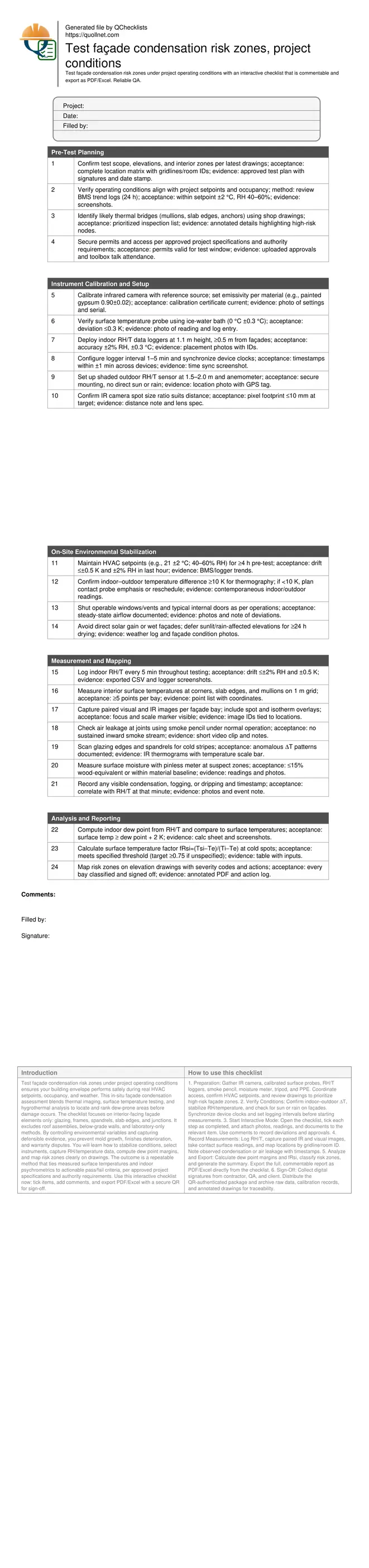
Test façade condensation risk zones, project conditions
Definition: Test façade condensation risk zones under project operating conditions to identify dew-prone surfaces using on-site measurements and thermography for contractors, QA engineers, and commissioning teams.
- Identify dew-prone surfaces under real HVAC and occupancy loads.
- Combine thermography, contact probes, and RH/T logging for evidence.
- Quantify risk using dew point margins and surface temperature factors.
- Interactive, commentable, export, QR code for authenticated field reports.
Test façade condensation risk zones under project operating conditions ensures your building envelope performs safely during real HVAC setpoints, occupancy, and weather. This in-situ façade condensation assessment blends thermal imaging, surface temperature testing, and hygrothermal analysis to locate and rank dew-prone areas before damage occurs. The checklist focuses on interior-facing façade elements only: glazing, frames, spandrels, slab edges, and junctions. It excludes roof assemblies, below-grade walls, and laboratory-only methods. By controlling environmental variables and capturing defensible evidence, you prevent mold growth, finishes deterioration, and warranty disputes. You will learn how to stabilize conditions, select instruments, capture RH/temperature data, compute dew point margins, and map risk zones clearly on drawings. The outcome is a repeatable method that ties measured surface temperatures and indoor psychrometrics to actionable pass/fail criteria, per approved project specifications and authority requirements. Use this interactive checklist now: tick items, add comments, and export PDF/Excel with a secure QR for sign-off.
- Establish reliable, repeatable field methods to find and rank condensation-prone façade areas under live HVAC and occupancy. Combine indoor RH/temperature logging, infrared thermography, and contact measurements to validate dew point margins with clear acceptance criteria and photographic evidence.
- Reduce risk of mold, corrosion, finish failures, and occupant complaints by stabilizing interior conditions and verifying surface temperatures at known thermal bridges. Document findings with paired visual/IR images, timestamped logs, and location-referenced drawings that stand up to technical scrutiny.
- Interactive online checklist with tick, comment, and export features secured by QR code. Facilitate collaboration among contractors, QA inspectors, and commissioning teams while preserving an authenticated audit trail for handover and future maintenance planning.
- Translate measurements into decisions: compute dew point from indoor RH/temperature, compare with measured surface temperatures, and calculate fRsi at cold spots. Flag nonconforming zones, assign corrective actions, and produce a concise, defensible report aligned with project specifications.
Pre-Test Planning
Instrument Calibration and Setup
On-Site Environmental Stabilization
Measurement and Mapping
Analysis and Reporting
Practical Methods and Acceptance Cues
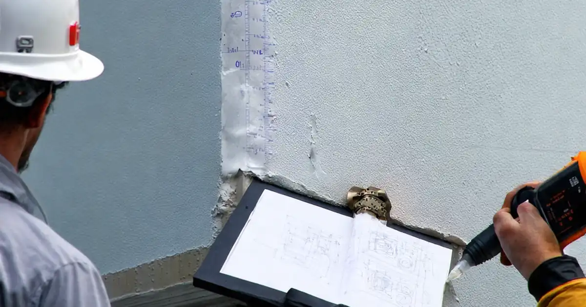
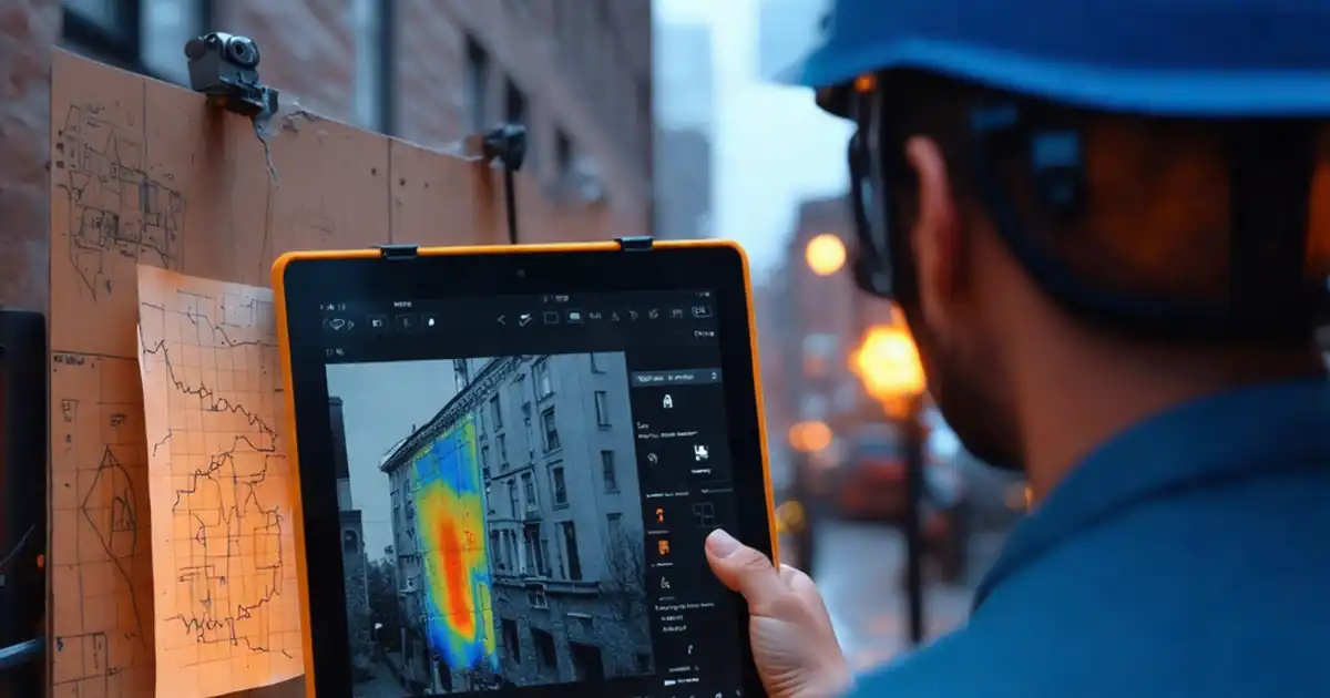
Accurate condensation risk testing blends thermography, contact surface readings, and psychrometric analysis. Begin by stabilizing the building to normal operating setpoints, then pair infrared imaging with spot temperature probes at the same locations to validate emissivity assumptions. Use indoor RH/temperature logging to compute dew point while scanning façade corners, slab edges, mullions, and glazing perimeters. Acceptance hinges on maintaining a dew point margin: interior surface temperatures should remain at least 2 K above the indoor dew point during the test window. For deeper insight, calculate the surface temperature factor fRsi at detected cold spots to rank severity and guide remediation. Real jobsite examples include cold stripes at spandrel insulation discontinuities and corner frames showing low fRsi due to thermal bridging. Deliverables must include paired IR/visual photos, timestamped data, and location-referenced notes that can be rechecked later without ambiguity.
- Validate IR findings with contact probe at identical points.
- Keep surface temperature ≥ dew point + 2 K.
- Use consistent 1 m grid to compare bays.
- Archive raw CSV logs and calibration records.
Environmental Stabilization and Timing
Field results depend on steady indoor conditions and suitable temperature differentials. Aim for an indoor–outdoor delta of at least 10 K to sharpen thermal patterns. If weather limits that delta, emphasize contact probes and extend logging to capture transient risks during occupancy peaks. Control solar gains and wet surfaces, which mask cold spots or mimic them through evaporative cooling. Coordinate with operations to ensure windows and vents reflect typical use during the test. A minimum of four hours of pre-test stabilization keeps drift within tight tolerances, while five-minute logging intervals capture short-lived events, such as morning humidity spikes from cleaning or occupancy surges. Document any deviations and test impacted elevations later if sun or rain interferes. This pragmatic approach preserves data integrity and avoids false positives or negatives that can misdirect corrective work.
- Target indoor–outdoor ΔT ≥ 10 K for IR.
- Stabilize HVAC for ≥ 4 hours pre-test.
- Avoid sunlit or rain-wet façades.
- Log RH/T every 5 minutes.
Documentation, Mapping, and Common Pitfalls
Defensible reports tie measurements to exact locations, times, and instruments. Build a location matrix by gridline and room ID, and tag every IR image and surface reading to that matrix. Show raw logger data, dew point calculations, and fRsi computations for cold spots, then color-code elevation drawings: green (pass), amber (monitor), red (action). Typical pitfalls include wrong emissivity settings on reflective frames, unsteady HVAC during scanning, and missing visual pairs for IR images. Mitigate by using matte tape dots on reflective surfaces, confirming setpoints with BMS trends, and photographing context with a scale marker. Close by issuing corrective actions with owners and timelines, such as sealing air leaks, adding insulation at spandrels, or adjusting ventilation controls, then plan a follow-up verification under the same operating conditions.
- Tag every image to a grid location.
- Include raw data with calculations.
- Use matte tape for reflective targets.
- Issue actions and schedule retest.
How to Use This Interactive Condensation Risk Testing Checklist
- Preparation: Gather IR camera, calibrated surface probes, RH/T loggers, smoke pencil, moisture meter, tripod, and PPE. Coordinate access, confirm HVAC setpoints, and review drawings to prioritize high-risk façade zones.
- Verify Conditions: Confirm indoor–outdoor ΔT, stabilize RH/temperature, and check for sun or rain on façades. Synchronize device clocks and set logging intervals before starting measurements.
- Start Interactive Mode: Open the checklist, tick each step as completed, and attach photos, readings, and documents to the relevant item. Use comments to record deviations and approvals.
- Record Measurements: Log RH/T, capture paired IR and visual images, take contact surface readings, and map locations by gridline/room ID. Note observed condensation or air leakage with timestamps.
- Analyze and Export: Calculate dew point margins and fRsi, classify risk zones, and generate the summary. Export the full, commentable report as PDF/Excel directly from the checklist.
- Sign-Off: Collect digital signatures from contractor, QA, and client. Distribute the QR-authenticated package and archive raw data, calibration records, and annotated drawings for traceability.
Call to Action
- Start Checklist Tick off tasks, leave comments on items or the whole form, and export your completed report to PDF or Excel—with a built-in QR code for authenticity.
- Download Excel - Façade Condensation Risk Testing (Operating Conditions)
- Download PDF - Façade Condensation Risk Testing (Operating Conditions)
- View Image - Façade Condensation Risk Testing (Operating Conditions)
Cite & Embed
“Façade Condensation Risk Testing (Operating Conditions) by Quollnet”
with a link to
this source page.
FAQ
Question: When is the best time to test façade condensation risk under operating conditions?
Question: What if the indoor–outdoor temperature difference is below 10 K?
Question: How do I handle reflective surfaces that distort infrared readings?
Question: What documentation will stakeholders accept as proof of compliance?
Related Articles
Broader reading and guidance connected to this checklist topic.




Rams Pack In Construction: Method Statement And Risk Assessment Template
Related Checklists
Keep the workflow moving with nearby templates chosen from similar checklist content.