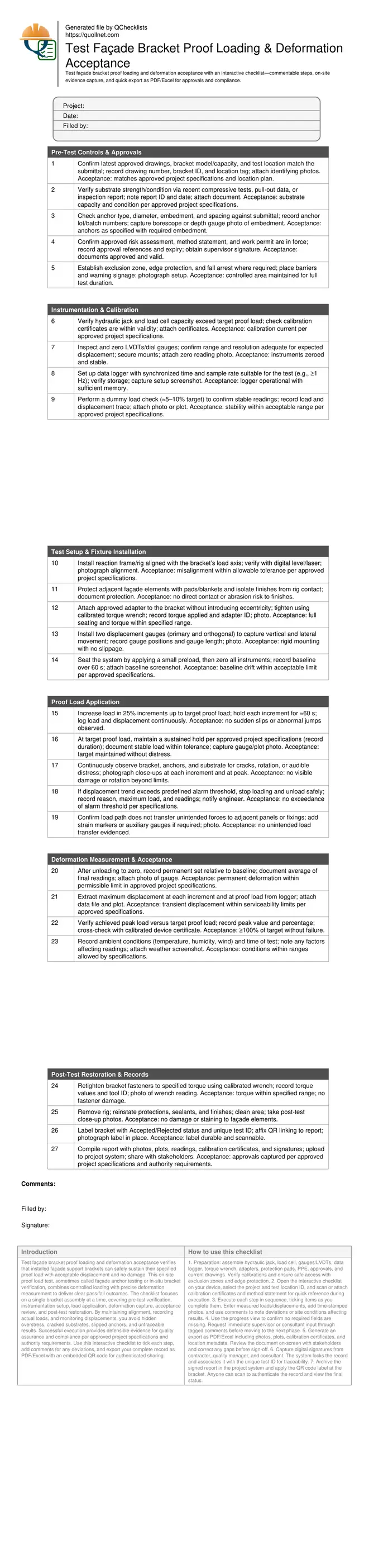
Test Façade Bracket Proof Loading & Deformation Acceptance
Definition: Test façade bracket proof loading and deformation acceptance ensures installed façade support brackets meet specified strength and serviceability under controlled on-site proof loads for quality managers, inspectors, and façade contractors.
- Confirms bracket capacity and serviceability under controlled proof loads.
- Measures displacement and permanent set using calibrated gauges or LVDTs.
- Captures photos, readings, and approvals for auditable acceptance decisions.
- Interactive, commentable, export, QR code for authenticated field records.
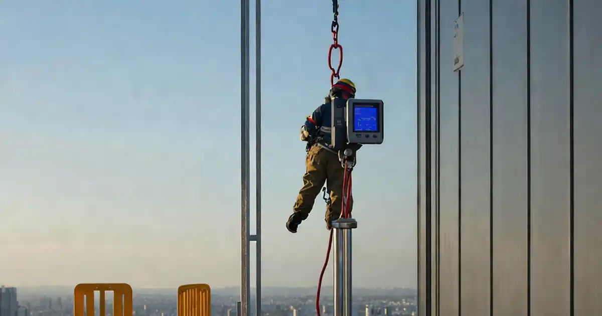
Test façade bracket proof loading and deformation acceptance verifies that installed façade support brackets can safely sustain their specified proof load with acceptable displacement and no damage. This on-site proof load test, sometimes called façade anchor testing or in-situ bracket verification, combines controlled loading with precise deformation measurement to deliver clear pass/fail outcomes. The checklist focuses on a single bracket assembly at a time, covering pre-test verification, instrumentation setup, load application, deformation capture, acceptance review, and post-test restoration. By maintaining alignment, recording actual loads, and monitoring displacements, you avoid hidden overstress, cracked substrates, slipped anchors, and untraceable results. Successful execution provides defensible evidence for quality assurance and compliance per approved project specifications and authority requirements. Use this interactive checklist to tick each step, add comments for any deviations, and export your complete record as PDF/Excel with an embedded QR code for authenticated sharing.
- This checklist standardizes on-site proof loading of façade brackets, ensuring each test uses calibrated equipment, controlled load steps, and aligned fixtures. It emphasizes objective measurements—load, displacement, and permanent set—so acceptance is traceable to approved project specifications without ambiguity.
- Field execution risks include off-axis loading, unverified anchors, and uncalibrated instruments that skew deformation results. The workflow mitigates these by requiring pre-test approvals, alignment checks, dummy runs, and continuous monitoring, producing defensible evidence that supports consultant and client sign-off.
- Interactive online checklist with tick, comment, and export features secured by QR code. Crews capture photos, time-stamped readings, and calibration certificates in real time, then generate consolidated PDF/Excel reports for immediate review, distribution, and archiving within the project’s quality system.
- Clear acceptance focuses on meeting target proof load, limiting transient displacement, and restricting permanent deformation within the permissible values stated in the approved project specifications. Post-test restoration and torque verification protect installed works and prevent latent defects.
Pre-Test Controls & Approvals
Instrumentation & Calibration
Test Setup & Fixture Installation
Proof Load Application
Deformation Measurement & Acceptance
Post-Test Restoration & Records
Methodology and Test Boundaries
This checklist covers a single installed façade bracket assembly subjected to a controlled proof load while monitoring displacement. The test includes pre-approval of submittals, calibration verification, alignment of the reaction rig, incremental loading to the specified proof load, a sustained hold, and full unloading to measure permanent set. It excludes full-system wind/sway testing, cyclic fatigue, and thermal movement evaluations; those require separate protocols. The procedure focuses on in-situ bracket verification where the load path is localized to the bracket and its anchors. Critical controls include avoiding eccentricity, maintaining a clean baseline after seating, and ensuring the substrate is not inadvertently damaged by the rig. Acceptance is based on achieving the specified proof load without distress and limiting both transient displacement and residual set.
- Test one bracket assembly per run for traceability.
- Maintain alignment to avoid eccentric loading effects.
- Record continuous load and displacement with timestamps.
- Hold at proof load per approved specifications.
- Measure permanent set only after full unloading.
Measurement, Tolerances, and Evidence Capture
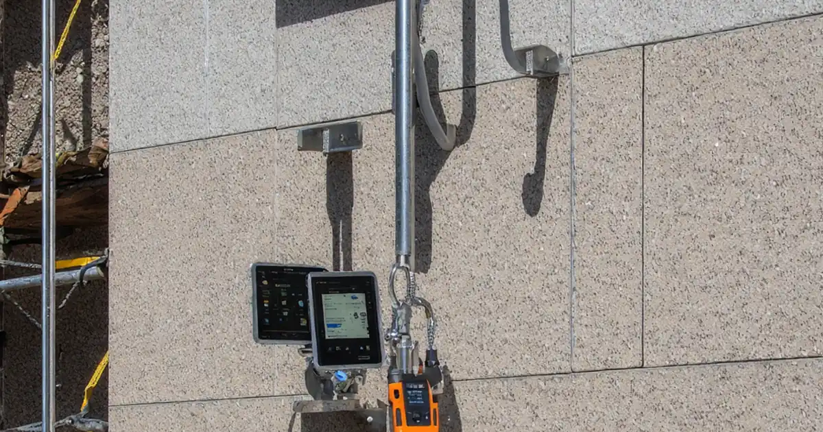
Accurate deformation capture requires rigidly mounted gauges, synchronized logging, and consistent zeroing. Use two gauges to distinguish primary movement from any lateral drift. Establish the baseline after a light seating load, then record displacement at each load step and throughout the hold. After unloading, measure permanent set against the baseline. Evidence must include calibration certificates, photos showing gauge placement and alignment, plots of load versus displacement, and the environmental record. Acceptance compares measured data with permissible limits for transient displacement and residual set stated in the approved project specifications and authority requirements. Where limits are not explicit, obtain written acceptance criteria before testing and document them within the test record.
- Zero instruments after seating load and before loading.
- Mount gauges on rigid references, not flexible cladding.
- Capture photos at each increment and peak hold.
- Attach raw logger files and marked plots.
- Document any drift and corrective actions.
Practical Field Cues and Common Pitfalls
Field failures often trace to off-axis fixtures, unverified anchor embedment, or expired calibrations. A quick dummy load validates the whole chain—from pump to sensor to logger—before critical loading. Watch for subtle rotation or crack initiation at the bracket toe and anchor edges; these may precede a displacement surge. Keep the exclusion zone enforced throughout; bystanders can bump gauges and corrupt data. When temperature or wind causes unstable readings, pause and stabilize shields or reschedule. If displacement approaches the alarm threshold, unload methodically and seek engineer guidance. Restore finishes and retighten fasteners immediately after testing to prevent moisture ingress or loosening.
- Confirm embedment depth with a photo or gauge.
- Use alignment tools to minimize eccentricity.
- Enforce a clear exclusion zone during testing.
- Pause if readings fluctuate with wind or vibration.
- Retighten and reseal immediately post-test.
How to Use This Checklist for On-Site Proof Load Tests
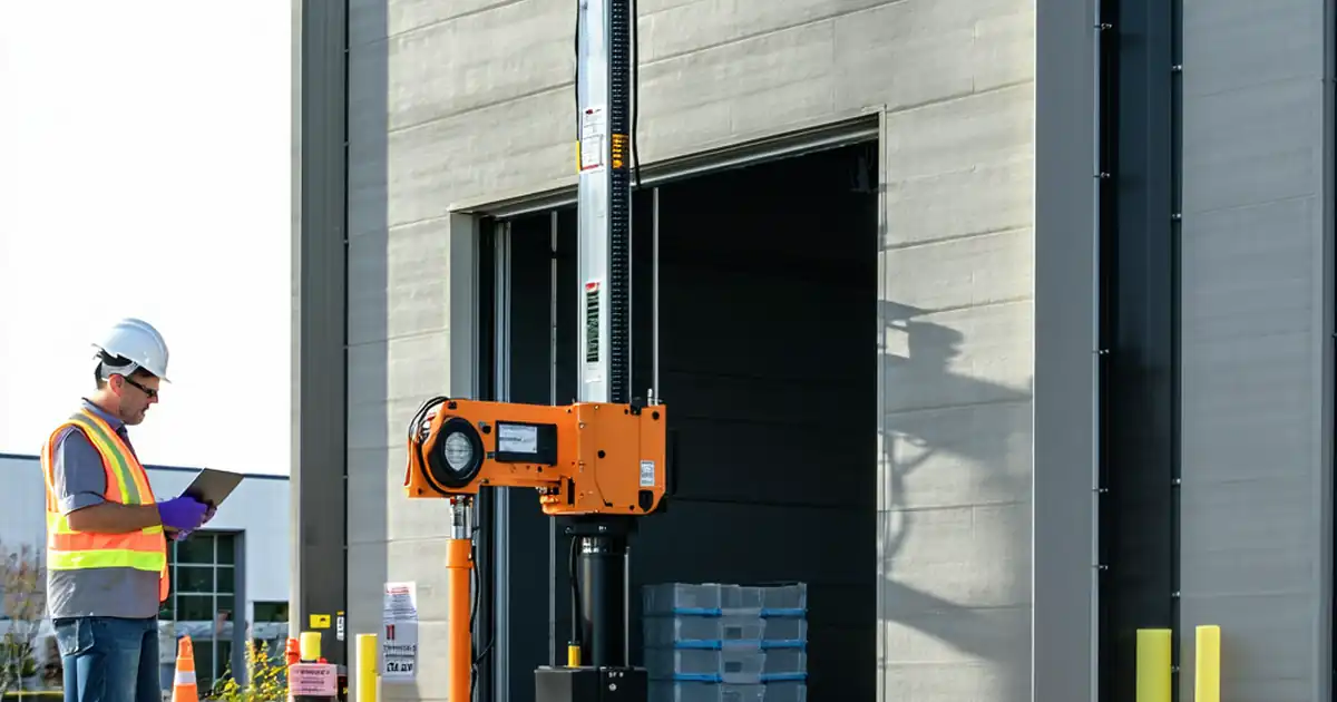
- Preparation: assemble hydraulic jack, load cell, gauges/LVDTs, data logger, torque wrench, adapters, protection pads, PPE, approvals, and current drawings. Verify calibrations and ensure safe access with exclusion zones and edge protection.
- Open the interactive checklist on your device, select the project and test location ID, and scan or attach calibration certificates and method statement for quick reference during execution.
- Execute each step in sequence, ticking items as you complete them. Enter measured loads/displacements, add time-stamped photos, and use comments to note deviations or site conditions affecting results.
- Use the progress view to confirm no required fields are missing. Request immediate supervisor or consultant input through tagged comments before moving to the next phase.
- Generate an export as PDF/Excel including photos, plots, calibration certificates, and location metadata. Review the document on-screen with stakeholders and correct any gaps before sign-off.
- Capture digital signatures from contractor, quality manager, and consultant. The system locks the record and associates it with the unique test ID for traceability.
- Archive the signed report in the project system and apply the QR code label at the bracket. Anyone can scan to authenticate the record and view the final status.
Call to Action
- Start Checklist Tick off tasks, leave comments on items or the whole form, and export your completed report to PDF or Excel—with a built-in QR code for authenticity.
- Download Excel - Façade Bracket Proof Loading & Deformation Acceptance
- Download PDF - Façade Bracket Proof Loading & Deformation Acceptance
- View Image - Façade Bracket Proof Loading & Deformation Acceptance
Cite & Embed
“Façade Bracket Proof Loading & Deformation Acceptance by Quollnet”
with a link to
this source page.

FAQ
Question: What proof load should I apply to a façade bracket during testing?
Question: How do I judge acceptable deformation and permanent set?
Question: Can I use dial gauges instead of LVDTs for deformation measurement?
Question: What should I do if readings drift during the hold period?
Related Articles
Broader reading and guidance connected to this checklist topic.


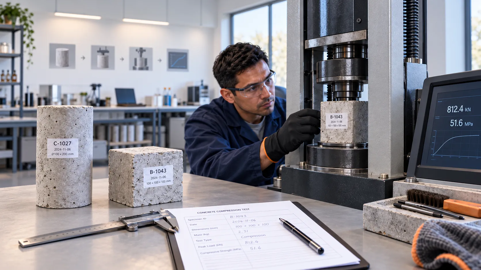
How To Perform a Concrete Compressive Strength Test: Cubes & Cylinders

Concrete Compressive Strength Acceptance Criteria: Aci 318-25 Vs En 206

Is It Important To Customize Your Qr Code And How To Do It?
Related Checklists
Keep the workflow moving with nearby templates chosen from similar checklist content.