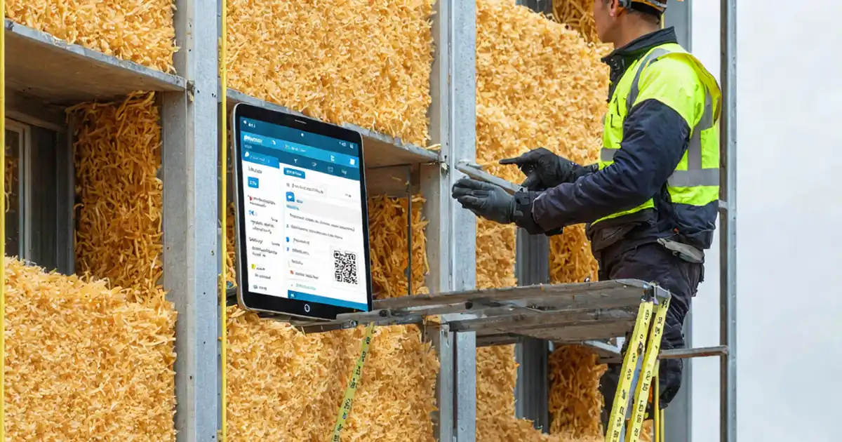
Façade–Roof Interface and Parapet Design Review Checklist
Definition: Review façade interface with roof build-up and parapet design helps architects, contractors, and inspectors verify waterproofing, thermal, and structural continuity at the roof-to-façade junction.
- Validate waterproofing, drainage, and air barrier continuity at junctions
- Reduce thermal bridges and moisture risks through coordinated detailing
- Apply measurable site checks with photos, readings, and approvals
- Interactive, commentable checklist with export and QR code verification
Review façade interface with roof build-up and parapet design ensures the roof edge, façade–roof junction, and parapet detailing work as a single, watertight, thermally continuous system. This checklist focuses on buildability, material compatibility, drainage paths, and the continuity of the air/vapour control layer across the interface. By concentrating on the junction between the roof membrane, upstands, cladding, cavity barriers, and parapet copings, it helps teams prevent water ingress, condensation, thermal bridging, and wind-driven rain failures. The outcome is a robust, documented installation that supports warranties and handover. It excludes unrelated structural framing checks or internal fit-out, and references only what can be inspected at the external interface. Use this to coordinate drawings, validate manufacturer details, and capture as-built evidence before concealment. Start in interactive mode to tick items, add location-tagged comments, and export as PDF/Excel via a QR-secured record for project sign-off.
- Coordinate the roof membrane, upstands, terminations, façade brackets, and parapet copings to achieve waterproof, airtight, and thermally continuous interfaces. Practical tolerances, photos, and material traceability reduce risk and support warranty alignment.
- Drainage performance is verified through correct falls, drip edges, scuppers, and overflow provision. Water testing, visual inspections, and obstruction checks limit ponding, backflow at the façade line, and hidden moisture traps in parapet zones.
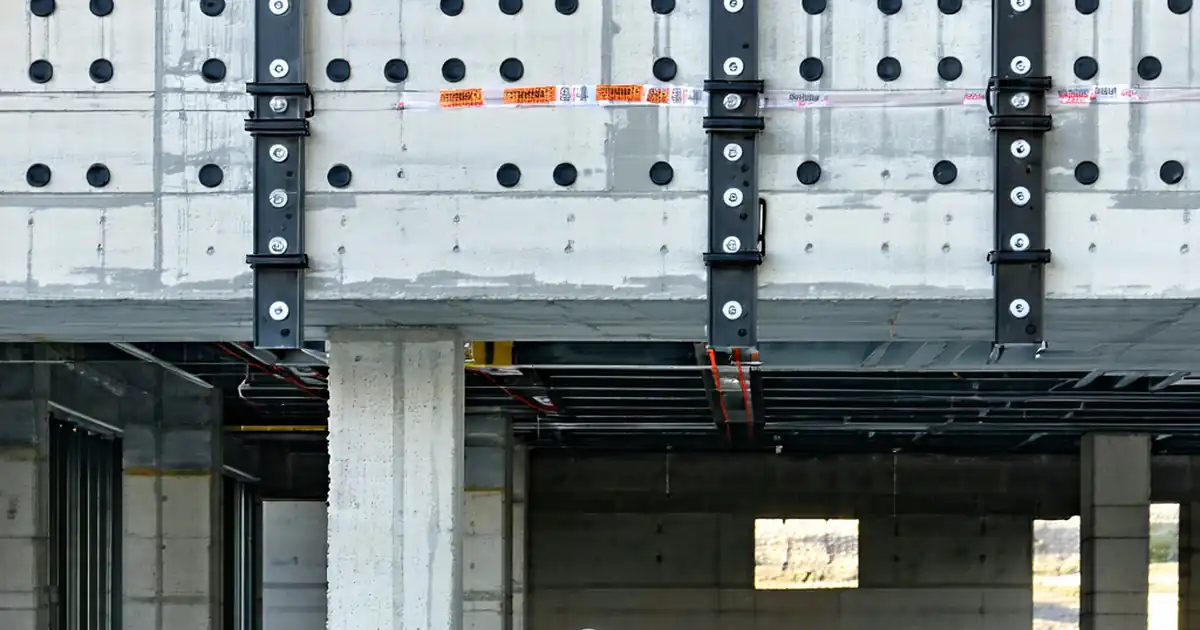
- Thermal and fire continuity is addressed with aligned insulation thicknesses, sealed AVCL laps, thermal breaks to brackets, and fitted cavity barriers. Measured gaps, torque logs, and product certificates provide reliable, auditable acceptance criteria.
- Interactive online checklist with tick, comment, and export features secured by QR code.
Design Inputs & Submittals
Waterproofing & Drainage Interface
Thermal & Fire Continuity
Parapet & Copings
Penetrations, Fixings & Tolerances
Coordinating the Façade–Roof–Parapet Interface
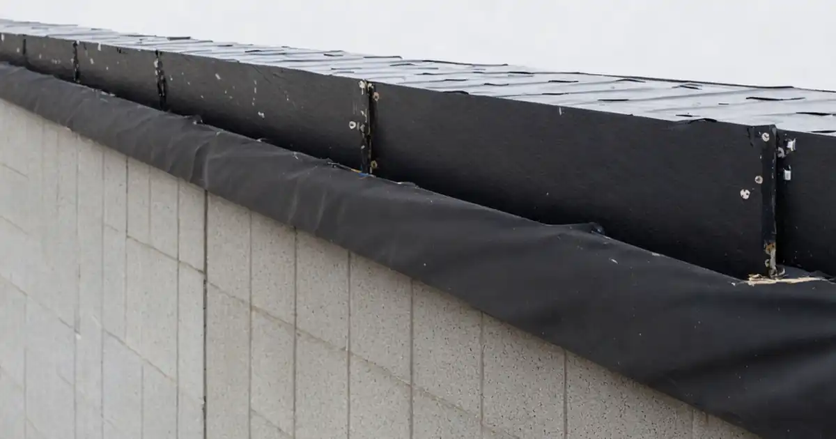
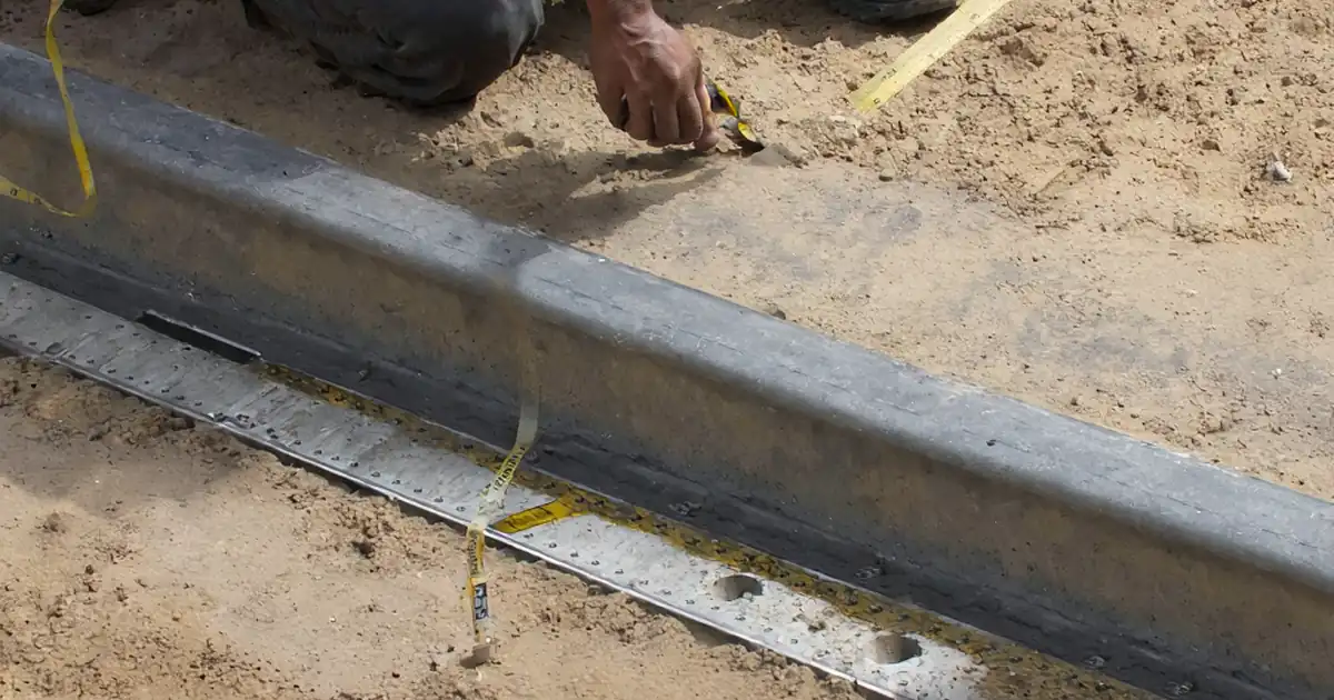
Successful interface delivery starts with coordination: drawings, shop details, and manufacturer instructions must agree on geometry, materials, and sequencing. The junction spans membrane upstands, AVCL connections, cladding support brackets, parapet copings, and drainage routes. Misalignment here creates chronic defects—water ingress, thermal bridging, and air leakage—that are expensive to remediate post-occupation. Establishing minimum upstand heights, drip edges clear of the façade, and compatible terminations guides installers and protects warranties. Before work begins, confirm who owns each line—roofing, façade, or metalwork—and lock in tolerances and inspection hold points. On site, verify falls with a laser, upstands with a tape, and document everything with location-tagged photos. Use mock-ups and manufacturer sign-offs to fix details early. This disciplined approach aligns teams and reduces ambiguity, ensuring construction matches design intent across the most failure-prone line of the building envelope.
- Agree ownership of every interface line and hold points
- Lock upstand, drip, and fall criteria before mobilization
- Use mock-ups to validate tricky corners and brackets
- Record evidence with location-tagged photos and registers
Waterproofing, Air, and Thermal Continuity
Continuity across systems avoids performance gaps. The roof membrane must rise at least 150 mm above the finished surface, turn into terminations, and integrate with counterflashings. The AVCL should be continuous on the warm side, with taped laps and sealed penetrations. Thermal continuity relies on insulation that matches field thickness at upstands, with tight joints and thermal breaks to brackets and balustrade posts. At the façade cavity, install cavity barriers/fire-stopping to maintain compartmentation and block smoke paths. Confirm sealant and membrane compatibility to stop chemical degradation. Use pull checks on tapes, probe seams, and measure laps; verify torque on brackets to avoid crushing thermal isolators. Every acceptance check should yield a photo, measurement, lot number, or signature, providing traceability that underpins warranty and compliance documentation.
- Upstands ≥ 150 mm above finished roof level
- AVCL laps taped; penetrations sealed and documented
- Insulation continuous; no gaps > 5 mm
- Thermal breaks installed and bolts torqued
Drainage, Testing, and Close-Out Evidence
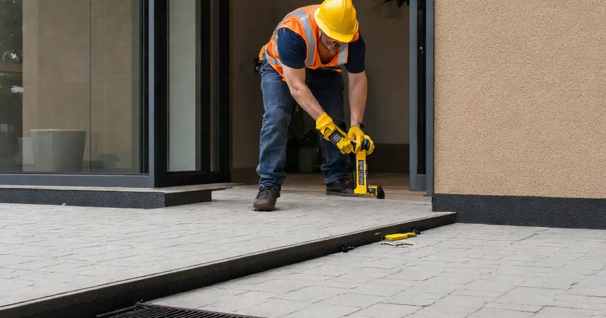
Parapets can trap water if scuppers, overflows, and drips are not coordinated. Ensure falls move water away from the façade, with formed drips that project clear of cladding. Conduct controlled hose or temporary flood tests where safe to verify scuppers, overflows, and seam integrity. After testing, no standing water deeper than 5 mm should remain near the façade line following a short drain-down. Protect outlets with guards and keep them clear of construction debris before handover. Finally, assemble a close-out package: approved interface details, compatibility letters, product data, torque logs, test records, and location-tagged photos. Export these records for sign-off to support warranties and future maintenance.
- Test scuppers and overflows with controlled water flow
- Confirm drips project water clear of cladding
- No ponding > 5 mm after drain-down
- Compile tests, photos, lots, and approvals
How to Use This Interactive Interface Review Checklist
- Preparation: gather approved drawings, manufacturer details, AVCL/membrane data sheets, torque tools, laser/tape, 2 m straightedge, hose, PPE, and the project document register.
- Walk the roof edge and parapets to identify inspection locations. Mark zones (grid references) for consistent photos and test logs.
- Open interactive mode on a mobile/tablet. Tick items as completed, attach photos, and add comments with location tags for each interface detail.
- Record measurements (falls, heights, laps, torque) directly in item comments. Capture lot numbers and installer signatures where required.
- If issues arise, flag items, assign actions, and set due dates. Reinspect flagged points and update with new photos and notes.
- Export as PDF/Excel for review meetings. Use the QR-secured link to authenticate records and share with stakeholders.
- Sign-Off: collect digital signatures from contractor, consultant, and client representatives; archive the final export in the project register.
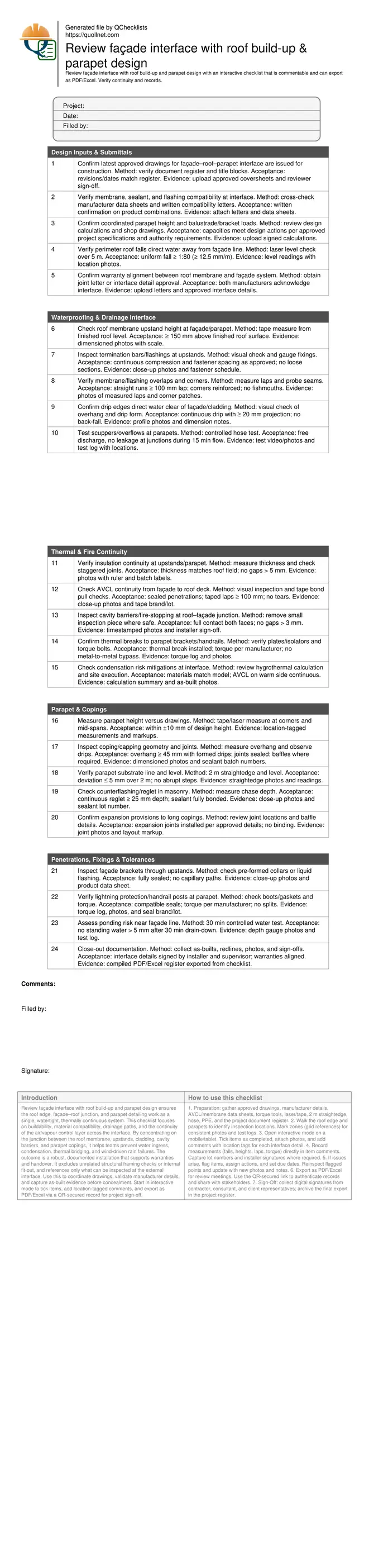
Call to Action
- Start Checklist Tick off tasks, leave comments on items or the whole form, and export your completed report to PDF or Excel—with a built-in QR code for authenticity.
- Download Excel - Façade–Roof Interface & Parapet Review
- Download PDF - Façade–Roof Interface & Parapet Review
- View Image - Façade–Roof Interface & Parapet Review
Cite & Embed
“Façade–Roof Interface & Parapet Review by Quollnet”
with a link to
this source page.

FAQ
Question: What minimum upstand height should I aim for at the façade–roof junction?
Question: How do I seal façade support brackets that penetrate the roof upstand?
Question: When should water testing be performed at parapet scuppers and overflows?
Question: What documents prove compatibility and support warranties at the interface?
Related Articles
Broader reading and guidance connected to this checklist topic.

Requisition Form: Materials, Services, Budget Control, And Logs



Is It Important To Customize Your Qr Code And How To Do It?

Related Checklists
Keep the workflow moving with nearby templates chosen from similar checklist content.