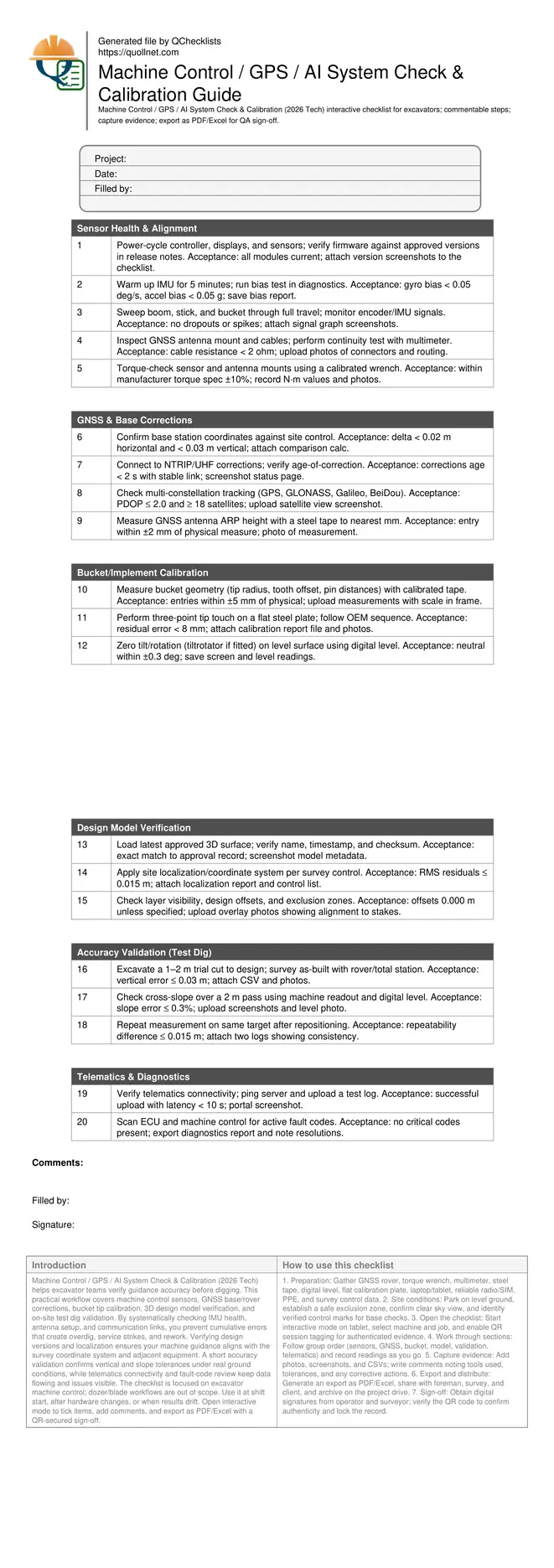
Machine Control / GPS / AI System Check & Calibration Guide
Definition: Machine Control / GPS / AI System Check & Calibration (2026 Tech) is a field-ready checklist for excavator crews and surveyors to verify sensors, GNSS corrections, design models, and on-site calibration accuracy.
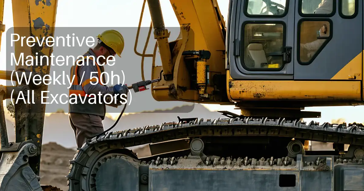
- Verify sensor health and alignment before earthmoving begins.
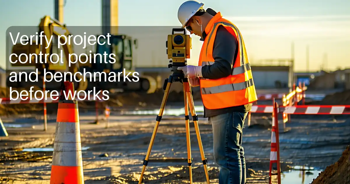
- Confirm GNSS/base corrections for consistent centimetre-level positioning.
- Calibrate bucket tip and validate accuracy with a test dig.
- Interactive, commentable, export, QR code for verifiable sign-off.
Machine Control / GPS / AI System Check & Calibration (2026 Tech) helps excavator teams verify guidance accuracy before digging. This practical workflow covers machine control sensors, GNSS base/rover corrections, bucket tip calibration, 3D design model verification, and on-site test dig validation. By systematically checking IMU health, antenna setup, and communication links, you prevent cumulative errors that create overdig, service strikes, and rework. Verifying design versions and localization ensures your machine guidance aligns with the survey coordinate system and adjacent equipment. A short accuracy validation confirms vertical and slope tolerances under real ground conditions, while telematics connectivity and fault-code review keep data flowing and issues visible. The checklist is focused on excavator machine control; dozer/blade workflows are out of scope. Use it at shift start, after hardware changes, or when results drift. Open interactive mode to tick items, add comments, and export as PDF/Excel with a QR-secured sign-off.
- Prevent rework and downtime by confirming sensor health, GNSS/base corrections, and bucket geometry before excavation. Consistent centimetre-level accuracy reduces overdig, protects services, and speeds production while supporting traceable, defensible quality records across shifts and subcontractors.
- Validate the loaded 3D design and coordinate system against site control to avoid mismatches between machines, survey rovers, and as-built checks. Early detection of version drift and projection errors eliminates costly redigs and enables confident dig-to-design on every pass across changing work areas.
- Interactive online checklist with tick, comment, and export features secured by QR code.
- Close the loop with a practical test dig, slope and repeatability checks, then telematics and fault-code reviews. Capture screenshots, photos, and CSVs as evidence, enable remote oversight, and distribute QR-authenticated PDFs/Excels for sign-off, audits, and handover without delaying production or safety briefings.
Sensor Health & Alignment
GNSS & Base Corrections
Bucket/Implement Calibration
Design Model Verification
Accuracy Validation (Test Dig)
Telematics & Diagnostics
Sensor chain readiness and GNSS/base corrections
Begin with a stable sensor chain. Warm the IMU to stabilize bias, then confirm encoder and angle sensors produce smooth signals through full boom, stick, and bucket motion. Tight mechanical interfaces are essential; loose mounts magnify error, so torque-check hardware to specification. GNSS reliability depends on a rigid antenna mount, clean cable runs, and a trustworthy corrections source. Validate the base coordinates against site control, then confirm a healthy constellation mix with low PDOP. Keep age-of-correction short to prevent drift during digging. These steps prevent stacking errors that otherwise produce centimetres of vertical miss across the work area. Document each check with screenshots and photos so variances can be traced quickly by remote support and supervisors. Where authority compliance applies, follow approved project specifications and authority requirements to align machine guidance with survey control and job documentation.
- Warm up IMU sensors for stable bias.
- Torque-check mounts to manufacturer specifications.
- PDOP <= 2.0 with multi-constellation tracking.
- Corrections age below 2 seconds.
- Log screenshots of satellite health.
Bucket tip calibration and practical accuracy validation
Accurate earthworks depend on precise bucket geometry and a clean tip calibration. Measure pin spacings, tooth offsets, and tip radius with calibrated tools, then carry out a three-point touch on a flat steel plate. Zero tilt/rotation on level ground using a digital level. After calibration, prove performance with a short test dig to design and survey the as-built using a rover or total station. Compare cut elevations and cross-slope against tolerances to confirm real-world accuracy, not just on-screen numbers. Repeat a measurement to verify repeatability; consistent results show the system is stable. Photograph setups and capture calibration and survey reports to create traceable evidence and to speed troubleshooting if performance drifts during production.
- Use a flat, rigid calibration plate.
- Three-point tip touch residual below 8 mm.
- Validate vertical error within 0.03 m.
- Repeatability within 0.015 m.
- Photograph measurement setups and results.
Design model control, telematics visibility, and diagnostics
Before work, confirm the correct 3D model and coordinate system are loaded. Version mismatches or wrong localizations cause machines to disagree with survey rovers, inviting rework. Verify model metadata and localization residuals, then perform a quick overlay to visible site features or stakes. Ensure telematics is online so screenshots, logs, and as-built CSVs synchronize for remote review. Low latency improves support when diagnosing issues mid-shift. Scan and address fault codes early to avoid degraded performance; many AI-enabled assists derate quietly when errors persist. Archive all evidence and produce a QR-authenticated report to share with supervisors and clients. This keeps audits smooth and gives the crew a defensible record of calibration and accuracy at the time of excavation.
- Verify model version checksum before work.
- Monitor telemetry latency under 10 seconds.
- Resolve fault codes before production.
- Archive calibration and test dig evidence.
- Share QR-secured report with stakeholders.
How to use this interactive calibration checklist
- Preparation: Gather GNSS rover, torque wrench, multimeter, steel tape, digital level, flat calibration plate, laptop/tablet, reliable radio/SIM, PPE, and survey control data.
- Site conditions: Park on level ground, establish a safe exclusion zone, confirm clear sky view, and identify verified control marks for base checks.
- Open the checklist: Start interactive mode on tablet, select machine and job, and enable QR session tagging for authenticated evidence.
- Work through sections: Follow group order (sensors, GNSS, bucket, model, validation, telematics) and record readings as you go.
- Capture evidence: Add photos, screenshots, and CSVs; write comments noting tools used, tolerances, and any corrective actions.
- Export and distribute: Generate an export as PDF/Excel, share with foreman, survey, and client, and archive on the project drive.
- Sign-off: Obtain digital signatures from operator and surveyor; verify the QR code to confirm authenticity and lock the record.
Call to Action
- Start Checklist Tick off tasks, leave comments on items or the whole form, and export your completed report to PDF or Excel—with a built-in QR code for authenticity.
- Download Excel - Machine Control / GPS / AI System Check & Calibration
- Download PDF - Machine Control / GPS / AI System Check & Calibration
- View Image - Machine Control / GPS / AI System Check & Calibration
Cite & Embed
“Machine Control / GPS / AI System Check & Calibration by Quollnet”
with a link to
this source page.

FAQ
Question: How often should I run the machine control and bucket calibration?
Question: What accuracy should I expect, and how do I diagnose poor results?
Question: Do I need a local base station, or is a network RTK feed enough?
Question: What is the best way to manage design model changes mid-shift?
Related Articles
Broader reading and guidance connected to this checklist topic.


Open Ncrs At Taking-over / Dlp: What Happens At Handover And How To Escalate

Related Checklists
Keep the workflow moving with nearby templates chosen from similar checklist content.