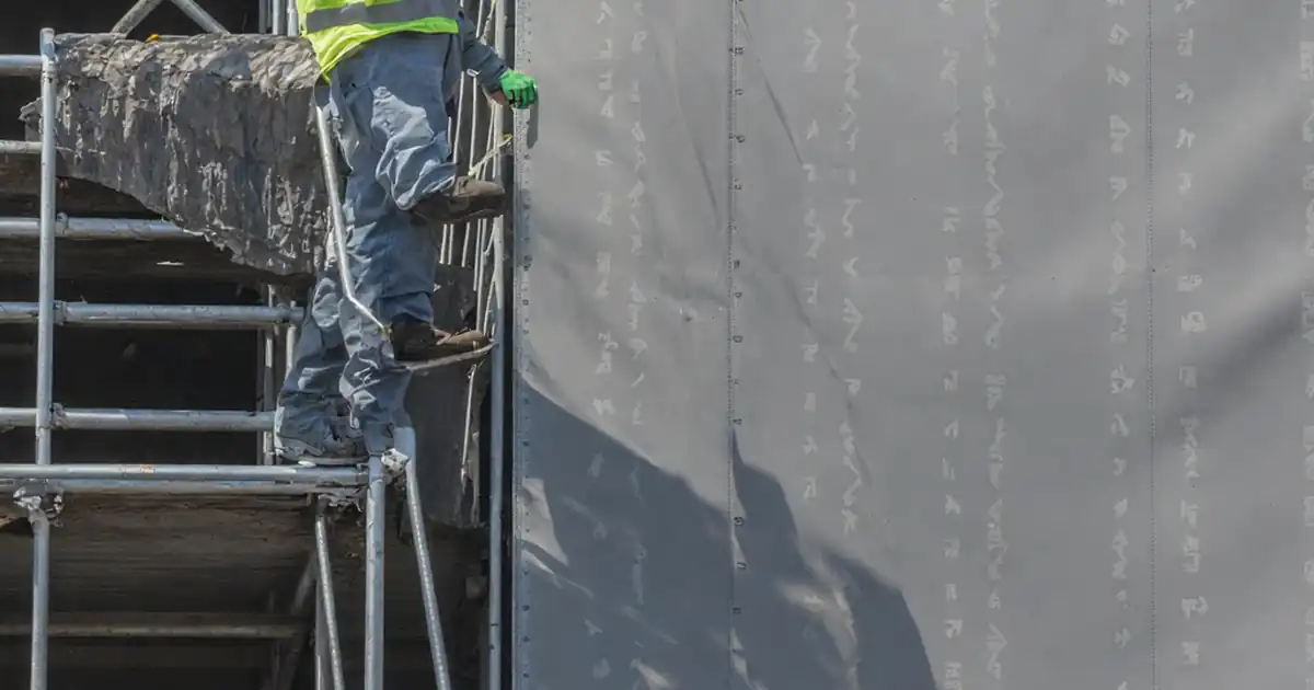
Inspect façade flashing installation above windows and doors
Definition: Inspect façade flashing installation above windows and doors for site inspectors and superintendents, verifying water-shedding geometry, compatible materials, and WRB integration to achieve durable, leak-resistant, and specification-compliant head details.
- Confirm slope, end dams, and drip edges shed water reliably.
- Verify compatible metals, sealants, and fasteners with documented evidence.
- Check shingle-fashion WRB integration and clear drainage paths.
- Interactive, commentable checklist with export and QR code verification.
Inspect façade flashing installation above windows and doors to ensure water stays out of the building envelope. This inspection targets window head flashing, door head flashing, and through-wall or cavity tray details installed above openings. The scope covers geometry, slope, terminations, fastenings, sealants, and integration with the weather-resistive barrier (WRB) immediately above lintels or structural heads. Done properly, these elements direct wind-driven rain outward, preventing leaks, damp insulation, corrosion, mold growth, and freeze–thaw damage to masonry or cladding. Outcomes include durable, low-maintenance façades, cleaner elevations without staining, and performance aligned with approved project specifications and authority requirements. You will verify material compatibility (metals, tapes, and sealants), dimension tolerances (slope, upstands, laps, overhangs), and functional drainage (weep paths and end dams) while capturing photos, measurements, and batch data as evidence. Use this interactive checklist to tick items, log comments with photos, and export a signed record to PDF or Excel, complete with a QR link for authentication.
- Focus on the head conditions above windows and doors: confirm outward fall, upstand height, end dams, laps, and overhangs, then verify WRB integration and clear weep paths. Capture photos, readings, and batch data for traceable compliance.
- Reduce water ingress, staining, and hidden decay by validating geometry, compatible materials, and correct fastening and sealing. Practical acceptance cues—like ≥2% fall, 100 mm upstands, and 100 mm laps—deliver predictable, repeatable outcomes across trades and shifts.
- Interactive online checklist with tick, comment, and export features secured by QR code. Field teams can attach photos, record measurements, tag locations, and generate shareable PDF/Excel reports for supervisors, designers, and authorities within minutes.
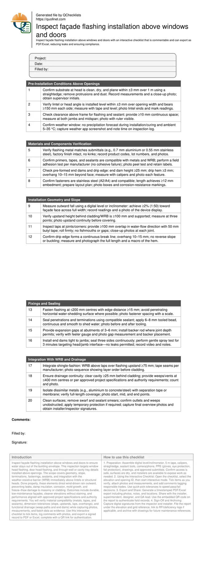
Pre-Installation Conditions Above Openings
Materials and Components Verification
Installation Geometry and Slope
Fixings and Sealing
Integration With WRB and Drainage
Why head flashing above openings is critical
Head flashings above windows and doors intercept water driven into the façade and redirect it outward before it can reach frames, insulation, or structure. Most failures trace back to missing end dams, insufficient outward fall, or poor WRB tie-in. Staining lines, damp reveals, and recurring interior leaks are telltale symptoms. A disciplined inspection verifies the gap above frames, lintel alignment, and substrate flatness to support straight, drip-forming flashings. It then confirms material compatibility so galvanic corrosion or sealant failures do not undermine the detail months later. Acceptance cues such as a visible drip hem, continuous laps, and documented slope measurements provide early assurance. On mixed-material façades—masonry, rainscreen, or EIFS—the same water-shedding principles apply, but tolerances and integration steps differ by system. Capture photos before cladding close-up to prove sequence and continuity, and require installer initials on each bay. These habits reduce remediation risk and protect warranties while keeping elevations clean and durable.
- Outward fall, end dams, and drip hem stop hidden water paths.
- WRB must lap over the upstand in shingle fashion.
- Material compatibility prevents galvanic corrosion and sealant failure.
- Capture photos before concealment for traceable compliance.
Geometry, tolerances, and verification methods
Reliable head flashings depend on measurable geometry. A minimum outward fall of 2% (1:50) moves water to the drip edge even in light winds. Upstands of at least 100 mm allow the WRB to overlap securely, and 100 mm laps at joints provide redundancy. Overhangs between 10–15 mm with a 3 mm hem create a sharp drip that breaks surface tension. Use a digital level for slope, calipers for hems, and a tape for laps and overhangs. Sealant beads should be 6–8 mm and properly tooled; overlarge beads trap water, undersized beads fail adhesion. Fastener spacing at 200 mm centres with adequate edge distance avoids oil-canning and blow-offs. Record actual measurements in the checklist for each opening, attach macro photos at joints, and tag locations on elevation drawings to speed punch-list clearance.
- Measure slope with a digital level—target ≥2% outward.
- Hem ≥3 mm and overhang 10–15 mm create a clean drip.
- Provide ≥100 mm upstand; lap joints ≥100 mm.
- Fasteners ≤200 mm centres with ≥15 mm edge distance.
Integration with WRB and drainage continuity
Even perfect metalwork leaks if upstream layers are reversed. The WRB must overlap the flashing upstand, not the other way around, and all seams require manufacturer-approved tape or liquid flashing. Corner patches and end dams stop lateral water migration into jambs. Maintain a clear cavity—typically ≥25 mm—so water can move to weeps or open joints at regular spacing. Where dissimilar metals meet, install separation membranes to avoid corrosion streaking and premature failure. Conduct a gentle hose test after sealing end dams to confirm the head–jamb interface performs before cladding conceals the detail. Document everything: photos of the sequence, lot labels of tapes and sealants, and signatures. This record supports approvals per approved project specifications and authority requirements and provides assurance when elevations are enclosed rapidly by downstream trades.
- Shingle-fashion layering: WRB over upstand, never reversed.
- Clear cavity ≥25 mm with regular weeps or vents.
- Seal end dams and corners; verify with spray test.
- Record labels, photos, and signatures for traceability.
How to Use This Interactive Inspection Checklist
- Preparation: Assemble digital level/inclinometer, 5 m tape, calipers, straightedge, sealant tools, camera/phone, PPE (gloves, eye protection, fall protection), drawings, and approved submittals. Confirm access is safe, surfaces are dry, and installers are available to expose work as needed.
- Using the Interactive Checklist: Open the checklist, select the elevation and opening ID, then start interactive mode. Tick items as you verify, attach photos and measurements, and add comments tagging responsible trades. Use quick-pick tolerances to speed pass/fail decisions.
- Export and Share: Generate a timestamped PDF/Excel export including photos, notes, and locations. Share with the installer, superintendent, designer, and QA lead. Use the embedded QR code on the report to authenticate field records.
- Sign-Off and Archiving: Capture digital signatures from the inspector and installer. File the report under the elevation and grid reference, link to RFI/deficiency logs if applicable, and archive with drawings for future maintenance references.
Call to Action
- Start Checklist Tick off tasks, leave comments on items or the whole form, and export your completed report to PDF or Excel—with a built-in QR code for authenticity.
- Download Excel - Façade Flashing Inspection Above Openings
- Download PDF - Façade Flashing Inspection Above Openings
- View Image - Façade Flashing Inspection Above Openings
Cite & Embed
“Façade Flashing Inspection Above Openings by Quollnet”
with a link to
this source page.

FAQ
Question: What minimum slope should a head flashing above windows and doors have?
Question: How long should laps be at joints in head flashings?
Question: Do I need end dams, and how high should they be?
Question: How do I integrate the flashing with the WRB correctly?
Related Articles
Broader reading and guidance connected to this checklist topic.


Concrete Compressive Strength Acceptance Criteria: Aci 318-25 Vs En 206

Is It Important To Customize Your Qr Code And How To Do It?

Master Construction Project Cashflow With Cashflowpot

Ncr Form Template (excel/pdf) – Non-conformance Report Format
Related Checklists
Keep the workflow moving with nearby templates chosen from similar checklist content.