G
Guest

construction · 18 checks

Duct Seismic Bracing Inspection

Where seismic bracing is specified for ductwork, inspection confirms whether the installed assembly matches the approved project details. The reviewed checklist supports a document-based inspection without asking the inspector to infer design requirements or accept conditions that cannot be verified.

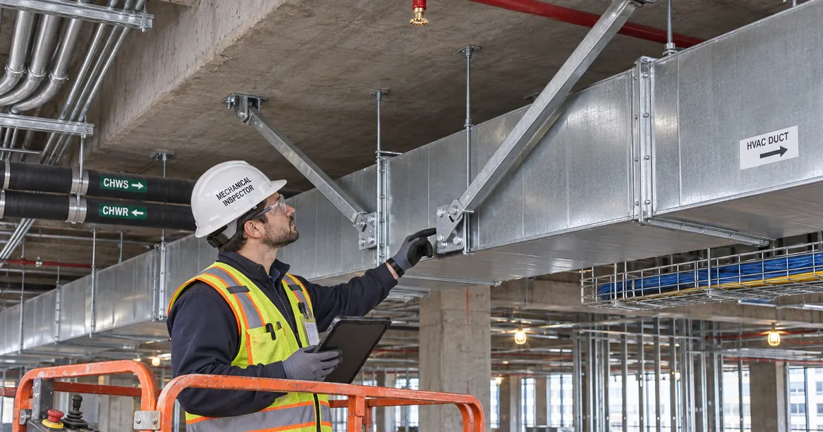
An inspector on a raised work platform holds a tablet and points to a bolted diagonal brace on a rectangular metal HVAC duct suspended beneath a concrete ceiling.

A duct seismic bracing inspection checks specified restraints, attachments, and movement clearances against approved project documents and applicable installation instructions.

  • Use approved drawings and product information as the inspection criteria.
  • Compare installed brace locations, geometry, and connections with approved details.
  • Verify tightening by the specified method, not visual appearance alone.
  • Keep discrepancies and unverifiable conditions unresolved pending documented disposition.

The checklist

Applicable Drawings

  1. Identify the current approved seismic bracing drawings and installation details applicable to the duct run being inspected.

Restraint Product Approval

  1. Verify that approved product information and applicable installation instructions are available for the installed restraint system.

Required Brace Locations

  1. Verify that each brace required by the approved drawings is present at its designated location.

Brace Spacing

  1. Compare installed brace spacing with the approved layout.

Restraint Directions

  1. Verify that installed brace directions match the approved transverse and longitudinal restraint details.

Restraint Types and Sizes

  1. Match installed restraint types and sizes to the approved product information.

Brace Angles

  1. Verify installed brace angles against the approved installation details.

Brace Condition

  1. Inspect brace members for visible damage or modifications not shown in the approved documents.

Duct-Side Attachments

  1. Verify that brace attachments to the duct or its support assembly match the approved connection details.

Structural Attachments

  1. Verify that structural attachment locations and supporting materials match the approved details.

Connection Hardware

  1. Compare installed connection hardware types, sizes, and quantities with the approved details.

Connection Condition

  1. Inspect connection hardware and attachment components for visible damage or modifications not shown in the approved documents.

Fastener Tightening

  1. Verify fastener tightening using the verification method specified in the applicable approved installation instructions; do not assume that visual appearance confirms tightening.

Visible Anchor Installation

  1. Compare visible anchor placement, spacing, edge distances, and installation conditions with the approved anchor details and applicable installation instructions.

Concealed Anchor Characteristics

  1. Verify that installation records identify the inspected anchor locations and demonstrate the required concealed installation characteristics. Record missing or insufficient evidence as unverifiable.

Movement Clearances

  1. Compare clearances between the braced duct assembly and adjacent construction or services with the movement clearances required by the approved documents.

Movement-Joint Connections

  1. Where movement joints are designated, verify that duct connections and associated restraints match the approved movement-accommodation details.

Unresolved Inspection Findings

  1. Record discrepancies, missing approval information, and unverifiable conditions by location. Keep affected items unresolved until the responsible project professional provides a documented disposition and any required corrective work is verified.

Preview the printable checklist

Preview page one below. Open the image or download the PDF for all pages.

First-page preview of the Duct Seismic Bracing Inspection printable checklist template.
Duct Seismic Bracing Inspection · Page 1 preview · Open image with all pages

At a glance

  • Approved project documents establish the required bracing arrangement and movement clearances.
  • Inspection covers the restraints, duct-side connections, structural attachments, and connection hardware.
  • Concealed anchor characteristics require location-specific installation evidence.
  • Missing criteria, discrepancies, and insufficient evidence must remain unresolved until appropriately addressed.

How to use the duct seismic bracing inspection checklist

  1. Identify the duct run and gather the current approved drawings, product information, and applicable installation instructions.
  2. Use the reviewed checklist to compare the installed restraints and connections with those documents, without substituting assumed design criteria.
  3. Use the specified verification methods and supporting installation records where visual inspection cannot establish compliance with the approved details.
  4. Record findings by location and keep affected items unresolved until documented disposition and verification of any required corrective work are complete.

Let approved documents define the inspection

The applicable drawings, restraint product information, and installation instructions provide the basis for comparison. Generic assumptions about spacing, brace angles, or anchor installation should not replace project-specific criteria.

  • Confirm that the documents apply to the duct run being inspected.
  • Record unavailable approval information rather than inferring requirements.

Review the restraint assembly as a connected system

Brace placement alone does not establish that an installation matches its approved details. The restraint arrangement, brace condition, duct-side attachments, structural attachments, and hardware all contribute to the inspection.

  • Compare installed geometry and components with the approved arrangement.
  • Distinguish visible damage or undocumented modifications from conditions supported by approved details.

Recognize the limits of visual verification

Visible hardware does not establish fastener tightening, and an exposed anchor connection does not demonstrate concealed installation characteristics. Use the specified tightening verification method and installation records that identify the inspected anchor locations.

  • Do not treat visual appearance as proof of tightening.
  • Record concealed conditions as unverifiable when supporting evidence is missing or insufficient.

Account for movement and close findings with evidence

Compare available movement space and designated movement-joint arrangements with the approved documents. Findings should identify the affected location and remain unresolved until the responsible project professional provides a documented disposition and any required corrective work is verified.

  • Assess clearances relative to adjacent construction and services.
  • Do not treat an unresolved discrepancy or unverifiable condition as accepted.

wael ali's photo
wael ali
313
22
2
3

Frequently asked questions

Does this checklist establish where duct seismic bracing is required?

No. It applies where bracing is specified and uses approved project documents to establish the required locations and installation details. It does not supply design requirements.

Can fastener tightening be confirmed by looking at the connection?

Visual appearance alone does not confirm tightening. Verification must use the method specified in the applicable approved installation instructions.

How should concealed anchor characteristics be verified?

Installation records must identify the inspected anchor locations and demonstrate the required concealed installation characteristics. Missing or insufficient evidence should be recorded as unverifiable.

What happens when approved information is missing or an installation differs from the details?

Record the issue by location and keep the affected item unresolved until the responsible project professional provides a documented disposition and any required corrective work is verified.

Related Articles

Broader reading and guidance connected to this checklist topic.

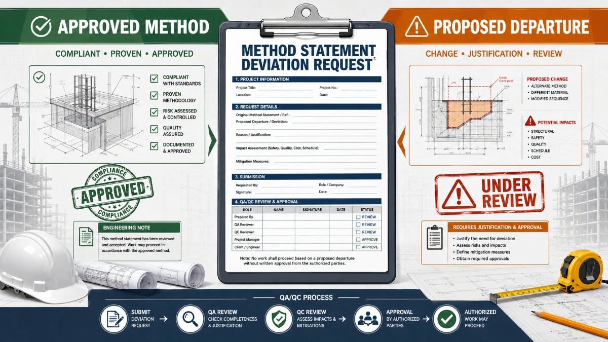
Method Statement Deviation Request Form: When The Approved Method Changes
M
en
Method Statement Deviation Request Form: When The Approved Method Changes
EN
Method Statement Deviation Request Form: When The Approved Method Changes

Use a method statement deviation request form when a contractor needs to depart from an approved method, specification, sequence, material, inspection...

Article 2026-05-20
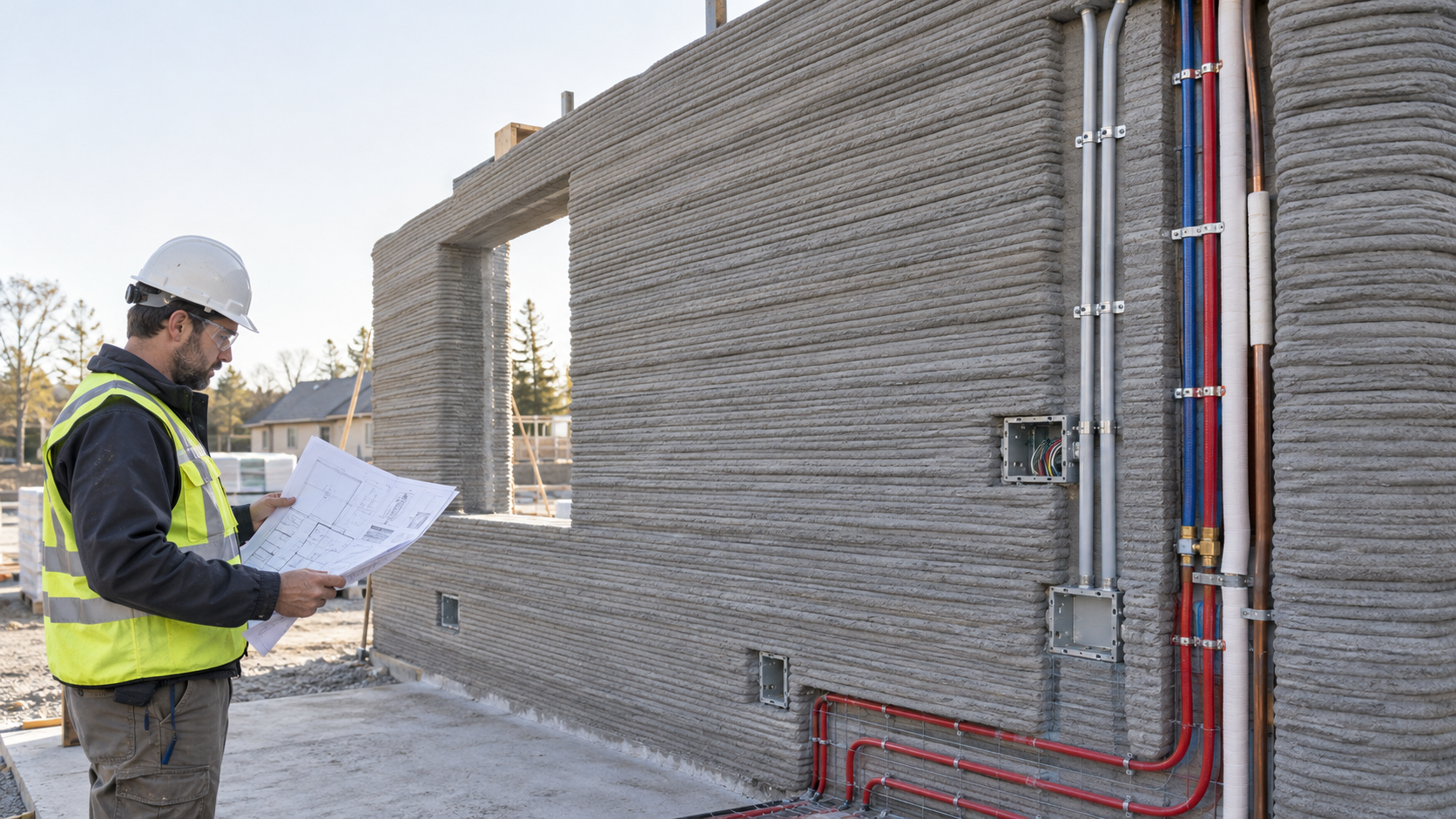
How Are Electrical And Plumbing Systems Installed In 3d Printed Houses? Full Mep Workflow
H
en
How Are Electrical And Plumbing Systems Installed In 3d Printed Houses? Full Mep Workflow
EN
How Are Electrical And Plumbing Systems Installed In 3d Printed Houses? Full Mep Workflow

Complete 3D printed house MEP workflow: electrical, plumbing, heating, gas and AC pipes before, during and after printing; pressure tests, release and...

Article 2026-11-09
Concrete Cube Vs Cylinder Strength: Why The 0.8 Rule Can Mislead
C
en
Concrete Cube Vs Cylinder Strength: Why The 0.8 Rule Can Mislead
EN
Concrete Cube Vs Cylinder Strength: Why The 0.8 Rule Can Mislead

Concrete cube vs cylinder strength explained: why geometry changes results, why 0.8/0.85 conversions can mislead, and how QA/QC should compare results...

Article 2026-09-11
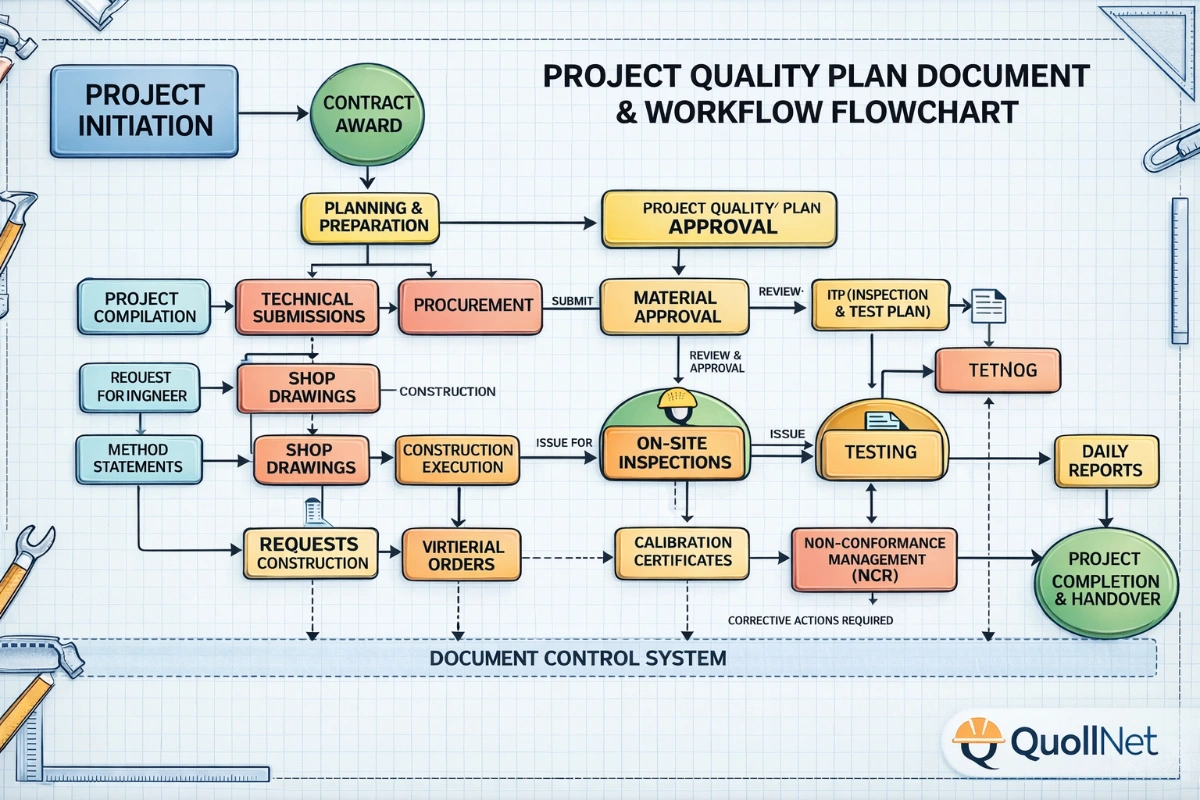
Project Quality Plan (project Manual) In Construction: Contents And Workflow Guide
P
en
Project Quality Plan (project Manual) In Construction: Contents And Workflow Guide
EN
Project Quality Plan (project Manual) In Construction: Contents And Workflow Guide

What is a Project Quality Plan (PQP) in construction? Learn what a PQP contains, how it protects contractors, and why it is essential for project acce...

Article 2026-04-07
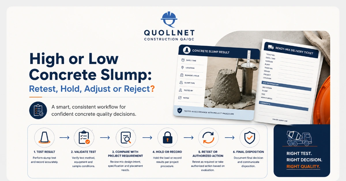
High Or Low Concrete Slump: Retest, Hold, Adjust Or Reject?
H
en
High Or Low Concrete Slump: Retest, Hold, Adjust Or Reject?
EN
High Or Low Concrete Slump: Retest, Hold, Adjust Or Reject?

What to do when concrete slump is high or low: confirm test validity, compare with project requirements, hold, retest, adjust only if authorized, and ...

Article 2026-08-11

Related Checklists

Keep the workflow moving with nearby templates chosen from similar checklist content.

A worker wearing a white hard hat and safety glasses touches the sealed, screw-fastened flange where a round metal branch duct connects to a rectangular metal duct. image
D
construction
Duct Branch Take-Off Connection Inspection Guide
Construction
Duct Branch Take-Off Connection Inspection Guide

A branch take-off connects a branch duct to the main duct. Inspection should establish whether the installed connection matches the approved design an...

A worker wearing a hard hat, safety glasses and reflective vest holds plans while looking at a rectangular metal duct supported by a horizontal metal channel and threaded hanger rods. image
H
construction
Horizontal Rectangular Duct Hanger Inspection Guide
Construction
Horizontal Rectangular Duct Hanger Inspection Guide

A duct hanger inspection connects field observations to the approved support design. For horizontal rectangular ductwork, this means checking more tha...

Worker wearing a hard hat, safety glasses, gloves and a high-visibility vest touches a circular metal duct coupling with screws, sealant and black alignment marks. A portable work light is nearby. image
C
construction
Circular Duct Coupling & Slip-Joint Inspection Guide
Construction
Circular Duct Coupling & Slip-Joint Inspection Guide

A round duct connection can appear complete while concealing shallow insertion, a displaced gasket, or incomplete sealant coverage. This guide support...

Photo-realistic editorial image of a full-scale curtain wall façade mock-up in a structural testing laboratory, shown in three-quarter view. Hydraulic actuators apply lateral racking at the interstorey interface, with visible LVDT displacement transducers, strain gauge wiring, and a data acquisition unit displaying live plots. Technicians in PPE observe from a marked 2 m exclusion zone. Overhead daylight and work lights illuminate mullions, glazing edges, and movement joints. Clean, modern lab environment, 16:9 composition, no overlaid captions or watermarks. image
F
construction
Test façade mock-up for seismic movement performance
Construction
Test façade mock-up for seismic movement performance

Test façade mock-up for seismic movement performance where required establishes whether the proposed façade assembly can accommodate interstorey drift...

A worker in a hard hat and safety vest holds a metal end cap beside an open flat-oval duct with a black gasket. A technical drawing and a separate oval gasket lie on the table below. image
F
construction
Flat-Oval Duct Joint Assembly Inspection Guide
Construction
Flat-Oval Duct Joint Assembly Inspection Guide

A flat-oval duct joint requires inspection across both its straight sections and curved ends. This supporting guide explains how to use the approved c...