Test dynamic façade response to sun-tracking control sequences is a commissioning and QA checklist for façade engineers, BMS integrators, and site managers validating automated shading behavior, timing, and safety interlocks.
- Verify sensors, timebase, and ephemeris against independent references and tolerances.
- Simulate morning, midday, and afternoon sun paths; confirm accurate actuation.
- Validate overrides for wind, fire, and manual control with evidence logs.
- Interactive, commentable, export options with QR code for authenticated records.
The checklist
Pre-Test Verification
- Confirm latest approved control schematics and sun-tracking sequence narrative match the installed system; compare revision dates to project records. Acceptance: current IFC/approved issue. Evidence: annotated screenshots and responsible engineer’s initials.
- Disable conflicting schedules and legacy scenes so only sun-tracking logic is active during testing. Method: BMS override with timestamp. Acceptance: no parallel commands seen. Evidence: trend screenshot of command priorities.
- Verify actuator power supplies and protections. Method: measure output (e.g., 24 V DC or 230 V AC) with a calibrated multimeter. Acceptance: voltage within ±5% of nameplate. Evidence: photo of readings and panel ID.
- Inspect representative façade modules for free travel. Method: visual check and torque-limited jog. Acceptance: no binding; seals intact. Evidence: photos of tracks, cables, and end-stops.
Sensor and Timebase Validation
- Calibrate rooftop or façade illuminance sensors against a reference lux meter. Method: side-by-side reading. Acceptance: ±10% across 5 points (100–50,000 lx). Evidence: table of paired readings and meter serial numbers.
- Verify site GPS coordinates, timezone, and daylight saving settings in BMS. Method: compare to verified source and NTP status. Acceptance: lat/long within 0.01°, clock offset < 1 s. Evidence: configuration screenshots.
- Validate solar ephemeris engine. Method: compare BMS sun azimuth/elevation to an external calculator at three times. Acceptance: each within ±1°. Evidence: captured values with timestamps.
- Check weather inputs (wind/rain) change state correctly. Method: vendor simulator or safe functional test. Acceptance: input status transitions within 2 s. Evidence: I/O trend and device photos.
Control Sequence Simulation
- Simulate morning condition (sun elevation 10–20°). Method: BMS time-shift. Acceptance: façade issues open/tilt commands per sequence within 2 s. Evidence: command log export (CSV).
- Simulate midday condition (peak elevation). Method: BMS scheduler. Acceptance: slat angle setpoint tracks algorithm; measured position within ±3° of setpoint. Evidence: setpoint vs actual trend plot.
- Simulate afternoon condition mirroring morning. Acceptance: symmetrical behavior; no cumulative offset. Evidence: overlay of morning/afternoon response with time alignment.
- Introduce cloud transients. Method: step illuminance using sensor simulator. Acceptance: no more than 2 position changes per minute (anti-hunting). Evidence: event count and deadband settings screenshot.
- Check group commands and addressing. Method: broadcast vs group tests on a 10-module set. Acceptance: inter-module start-time skew ≤ 0.5 s. Evidence: time-synced video or high-speed log.
Physical Response Measurement
- Measure actuation delay from command to motion start. Method: stopwatch or 120 fps video. Acceptance: < 2 s. Evidence: timestamped clip and noted frame count.
- Measure full travel time 0–90° (and return). Method: timed cycle. Acceptance: within ±10% of manufacturer data. Evidence: recorded times and module IDs.
- Verify slat/blade angle accuracy. Method: digital inclinometer or photogoniometer at 0°, 30°, 60°, 90°. Acceptance: ±2°. Evidence: readings with calibration certificate reference.
- Check operational noise and vibration. Method: sound level meter at 1 m during motion. Acceptance: ≤ 60 dB(A). Evidence: SPL readings and device make/model.
- Assess motor temperature after 10 consecutive cycles. Method: IR camera. Acceptance: surface temperature ≤ 60 °C. Evidence: thermal images with emissivity setting noted.
Fail-safes and Overrides
- Verify wind override behavior per approved project specifications. Method: simulate wind above threshold (e.g., 12 m/s). Acceptance: safe position reached within 5 s. Evidence: alarm log and position trend.
- Test fire alarm interface per approved project specifications and authority requirements. Acceptance: required position achieved within 10 s; normal restored on reset. Evidence: cause-and-effect log excerpt.
- Confirm local manual override priority. Method: wall switch or maintenance HMI. Acceptance: local command takes precedence; BMS logs reason code. Evidence: video and event record.
- Check obstruction/protection function. Method: introduce soft block during close. Acceptance: current limit trips and reversal occurs. Evidence: video, fault code, and reset record.
Data Logging and Handover
- Verify trend logging cadence. Method: inspect historian settings. Acceptance: ≥ 1 Hz for position/state; time-synced to NTP. Evidence: configuration screenshot.
- Export as-built parameters, firmware versions, and device addresses. Acceptance: all modules listed with dates and lot numbers. Evidence: CSV/PDF attached to record.
- Capture as-left photos of representative elevations at key angles. Acceptance: geotagged images labeled with location and angle. Evidence: photo set uploaded to record.
- Obtain digital sign-offs from contractor, controls vendor, and client. Acceptance: all roles signed; deviations noted. Evidence: signed PDF with QR-authenticated link.
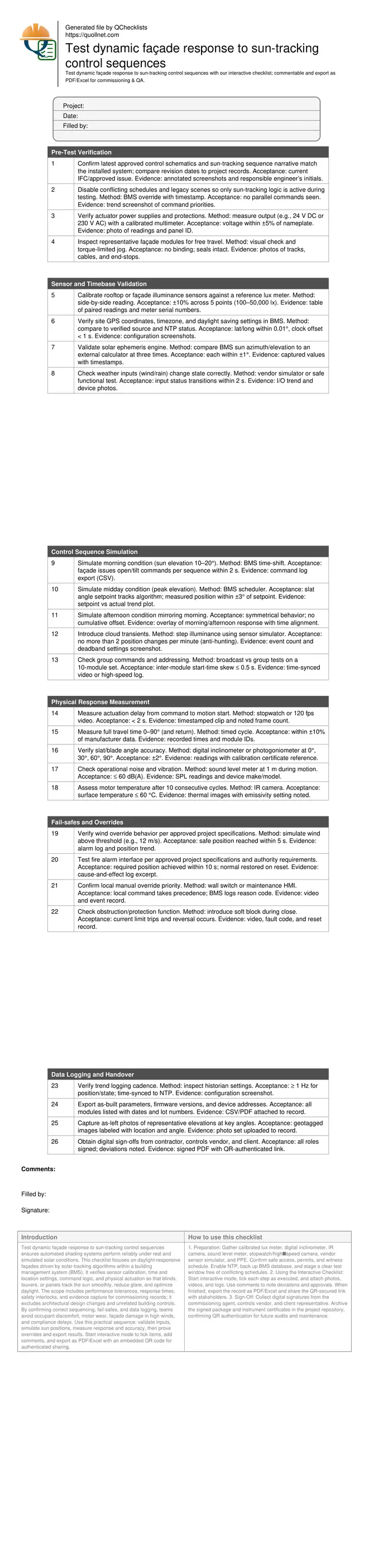
Preview the printable checklist
Preview page one below. Open the image or download the PDF for all pages.
At a glance
- Deliver a repeatable commissioning method that aligns sensors, timebase, and control logic with verified solar ephemeris. Capture timings, position accuracy, and energy-safe behavior under transient clouds and varying irradiance to prevent glare, reduce actuator wear, and protect façades during wind or alarm events.
- Demonstrate measurable performance: actuation delay under 2 s, slat angle accuracy within ±2°, synchronized group response, and stable behavior under cloud passages. Record evidence with photos, videos, instrument readings, and BMS logs to satisfy project specifications and stakeholder acceptance.
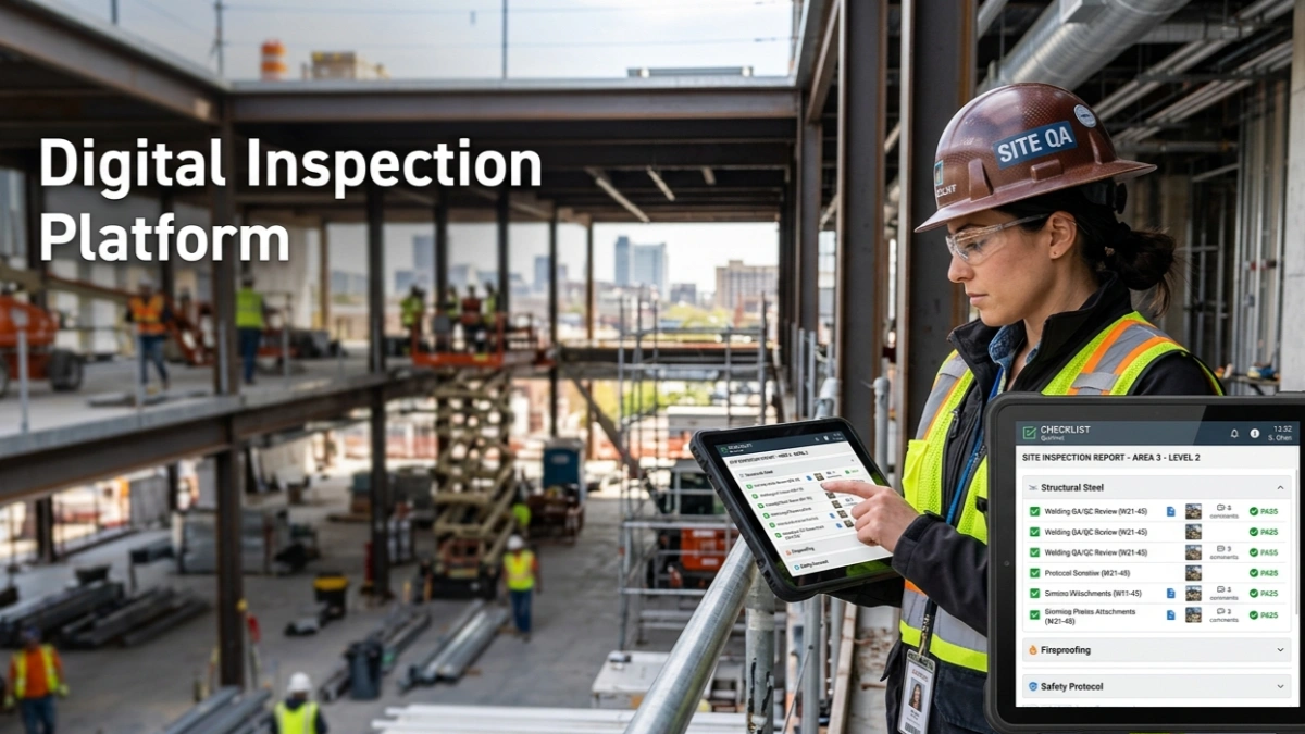
- Interactive online checklist with tick, comment, and export features secured by QR code.
How to Use This Interactive Sun-Tracking Façade Test
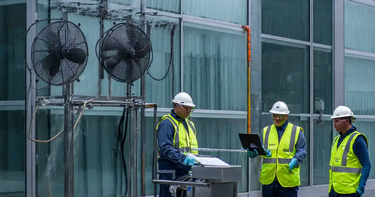
- Preparation: Gather calibrated lux meter, digital inclinometer, IR camera, sound level meter, stopwatch/high‑speed camera, vendor sensor simulator, and PPE. Confirm safe access, permits, and witness schedule. Enable NTP, back up BMS database, and stage a clear test window free of conflicting schedules.
- Using the Interactive Checklist: Start interactive mode, tick each step as executed, and attach photos, videos, and logs. Use comments to note deviations and approvals. When finished, export the record as PDF/Excel and share the QR-secured link with stakeholders.
- Sign-Off: Collect digital signatures from the commissioning agent, controls vendor, and client representative. Archive the signed package and instrument certificates in the project repository, confirming QR authentication for future audits and maintenance.
Establish reliable inputs and aligned timebase
Dynamic, sun-tracking façades are only as accurate as their inputs. Begin by confirming sensor calibration and the system clock against trustworthy references, then validate the solar ephemeris used to calculate azimuth and elevation. Small errors in latitude, timezone, or clock drift can translate into repeated daily misalignment, glare, and occupant complaints. Independent verification at morning, midday, and afternoon proves that the BMS algorithm is computing the sun’s position correctly before you stress actuators. Pair this with a quick mechanical health check to avoid attributing mechanical faults to software logic. On live projects, a 1 s clock offset or a 0.02° coordinate error has created several degrees of tracking error at the window line. With inputs and timebase controlled, subsequent sequence tests become conclusive, evidence-rich, and repeatable across elevations and orientations. Always document settings, reference instruments, and environmental conditions in the record to enable later audits, warranty support, and regression testing after software updates.
- Calibrate sensors with a traceable reference lux meter.
- Verify GPS, timezone, NTP, and daylight saving settings.
- Check solar azimuth/elevation within ±1° at three times.
- Inspect mechanical travel before sequence testing.
- Capture screenshots and photos as persistent evidence.
Prove sequence logic and physical response
Once inputs are sound, simulate the day. Use controlled morning, peak, and afternoon conditions to confirm that commands are issued promptly and that blades achieve setpoints within tolerance. Trend both setpoint and measured angle to expose drift or backlash. Measure actuation delay and full-travel time to quantify responsiveness. Introduce cloud transients to verify anti-hunting deadbands and rate limits that prevent rapid cycling and motor wear. Validate group control to ensure uniform appearance across a bay; even 0.5 s skew is visible on glass. Field teams often reveal hidden priority conflicts when a legacy scene still asserts control; resolve these before formal witnessing. Record all readings, videos, and logs with timestamps so stakeholders can re-create findings after handover, or when software patches modify behavior later.
- Simulate sun positions; verify prompt commands.
- Confirm blade angles within ±2° of setpoint.
- Trend setpoint vs actual to detect drift.
- Limit repositioning to ≤ 2 changes per minute.
- Keep inter-module skew ≤ 0.5 s.
Validate safety, overrides, and documentation
Safety and compliance depend on predictable overrides. Prove wind protection moves façades to a safe position quickly and restores normal tracking when the hazard clears, per approved project specifications. Test fire alarm behavior with the responsible party witnessing, and document the cause-and-effect. Confirm local manual stations can take priority for maintenance without leaving the BMS unaware. Verify obstruction detection to avoid damage. Finally, check data logging cadence and export all as-built details—firmware versions, device addresses, and settings—so that future maintenance can diagnose issues without guesswork. Attach photos and videos of representative bays from multiple elevations to demonstrate consistent performance. Archive results in an authenticated repository and link the signed record via a QR code for quick field retrieval during operations and audits.
- Demonstrate wind and fire overrides as specified.
- Verify manual priority and logged reason codes.
- Test obstruction detection and safe reversal.
- Trend at ≥ 1 Hz with synchronized timestamps.
- Export versions, addresses, and parameter sets.