Test Façade Gasket Continuity and Compression After Installation
Definition: Test façade gasket continuity and compression after installation with this field-ready checklist for façade inspectors and contractors, confirming continuous seals and adequate compression on installed glazing and rainscreen systems.
- Verify continuous seals across runs, corners, and transitions
- Measure compression with feeler gauges and pressure film
- Prevent water and air leaks through practical, repeatable field tests
- Interactive, commentable checklist; export and verify via QR code
Test façade gasket continuity and compression after installation using a structured, field-proven process. This checklist focuses on curtain wall gaskets, EPDM glazing seals, and rainscreen interfaces after units are fully installed, ensuring uninterrupted sealing and correct compressive contact. By verifying linear runs, corners, splices, and transitions, and by measuring actual compression with feeler gauges and pressure-sensitive film, you reduce risks of water ingress, air leakage, drafts, noise, and premature seal failure. The scope excludes chamber testing and full-system certification; instead it delivers rapid, repeatable field verification aligned with approved project specifications and authority requirements. Acceptance cues include uniform contact, documented torque where applicable, targeted compression percentage, and clean drainage paths. Outcomes include a tighter, more durable façade, validated evidence for warranty, and faster closeout with fewer punchlist returns. Use this interactive checklist to tick items, add photos and comments, and export results as PDF/Excel with a secure QR for traceability.
- Confirm gasket continuity across mullions, rails, corners, and splices, including concealed interfaces. Verify seating, joins, and drainage paths. Capture close-up photos at prescribed intervals and geotag evidence. Early detection limits rework, reduces infiltration risk, and supports faster project closeout with defensible QA records.
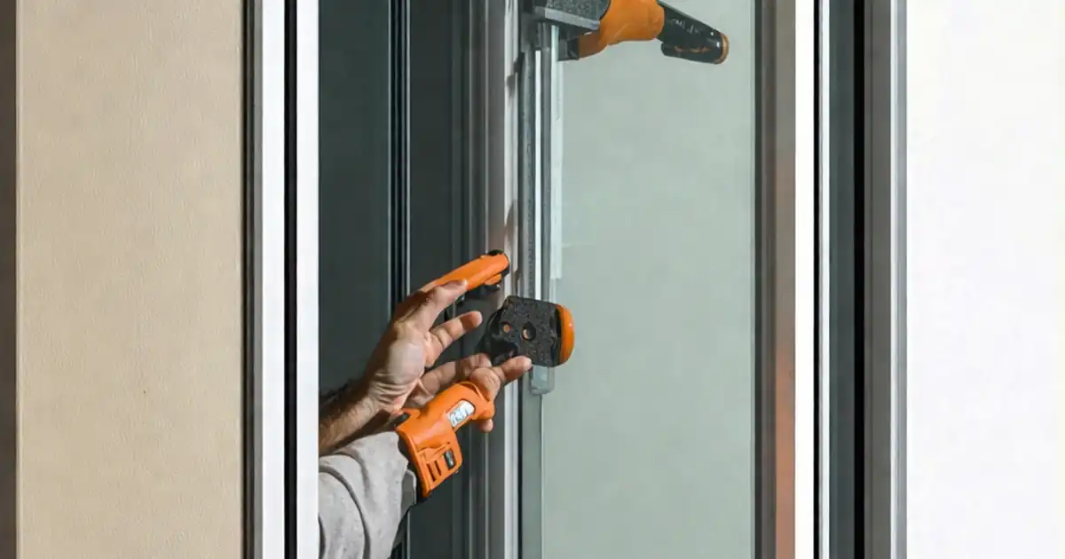
- Quantify compression using calipers for free thickness, feeler gauges for contact, and pressure-sensitive film for distribution. Correlate with torque readings where pressure plates or clips regulate bite. Document calculations against target compression ranges or approved project specifications and escalate only if patterns suggest systemic issues.
- Interactive online checklist with tick, comment, and export features secured by QR code.
Pre-Test Setup
Visual Continuity Inspection
Compression Verification
Air/Water Tightness Spot Checks
Documentation and Evidence
Corrective Actions and Sign-Off
Continuity: Where Gaskets Commonly Fail and How to Prove They Don’t
Continuity is more than an unbroken line; it is uninterrupted, effective contact along the entire seal path. Post-installation failures often appear at corners, terminations, splices, and mullion intersections where tolerances converge. Twisted gaskets, short cuts that shrink at corners, and adhesive gaps can create invisible capillary paths. Start with strong lighting, mirrors, and a borescope for concealed interfaces. Confirm the gasket is fully seated in its reglet or rebate and not rolled or stretched thin. Splices should be aligned and compressed evenly, with no fishmouths. Drainage and weeps must remain clear so trapped water cannot bridge into the interior. Acceptance cues include no visible daylight, no gaps exceeding 2 mm, and secure retention during a gentle 10 N pull. Document each transition with close-ups and a location grid. Solid photo evidence, paired with geotagging and unit IDs, delivers defensible continuity proof without disruptive dismantling.
- Corners and splices are the highest-risk discontinuity points
- Use mirrors and a borescope to see concealed paths
- No daylight; gaps over 2 mm are not acceptable
- Keep drainage and weeps open and unobstructed
- Label evidence by elevation, gridline, and unit ID
Quantifying Compression with Feeler Gauges, Film, and Torque
Compression must be measured, not assumed. Begin by recording the gasket’s free thickness and the installed thickness to calculate compression percentage. A simple feeler gauge confirms contact: a 0.10 mm blade should not slide in more than 10 mm at any location. Pressure-sensitive film provides a visible map of contact distribution; unprinted spans signal low or absent compression. Where pressure plates or clips control bite, verify torque using a calibrated wrench, then recheck contact. Typical acceptance targets are 25–35% compression, permanent set ≤10%, and uniform film print without unprinted runs over 20 mm, unless the approved project specifications define otherwise. Measure at multiple points per unit to capture variability, and log min/avg/max values. Photos of gauges at reading positions and film results with a ruler establish reliable evidence. This method triangulates compression through thickness change, tactile resistance, and pressure mapping.
- Calculate compression from free and installed thickness
- Feeler gauge depth ≤10 mm indicates adequate contact
- Film should show continuous, uniform pressure print
- Torque influences compression; verify with a calibrated wrench
- Photograph readings with a scale for traceability
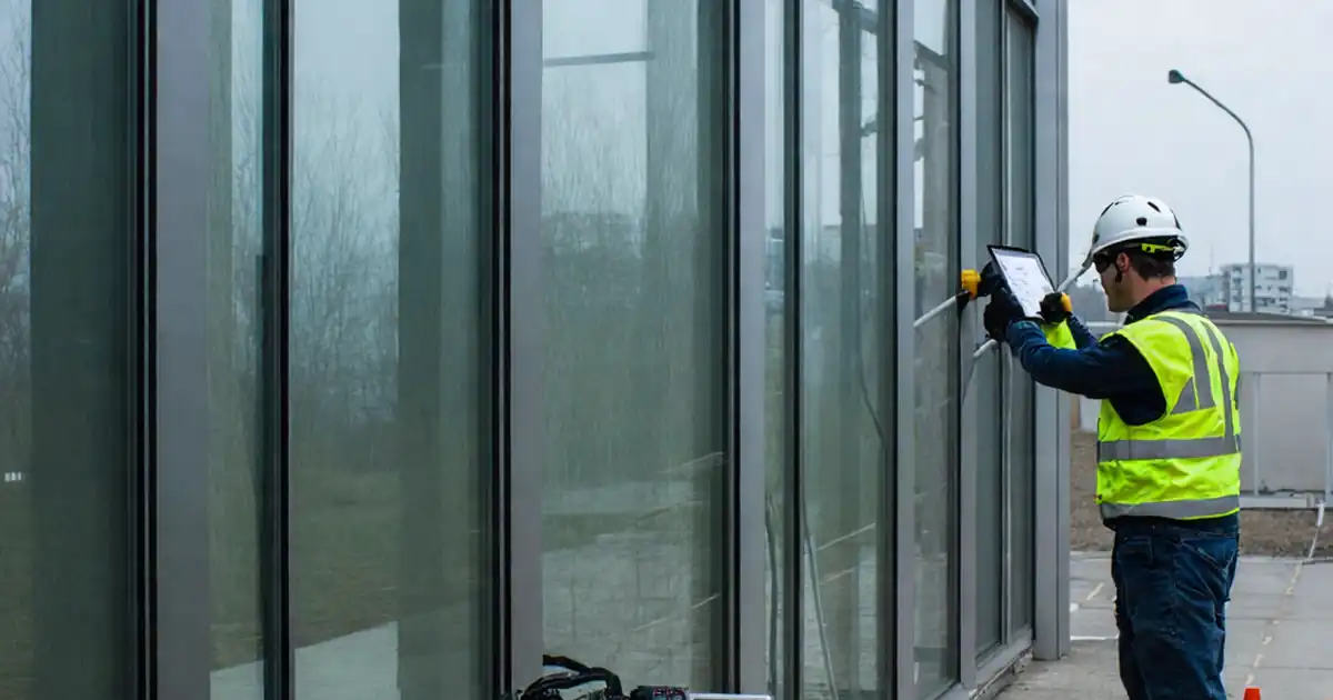
Spot-Checking Air and Water Tightness Without Full Chambers
You can validate the effects of continuity and compression using quick, non-destructive spot checks. A smoke pencil from the interior reveals pressure-driven leaks at joints; steady inward smoke indicates a pathway. Ultrasonic testing with an exterior tone source lets you scan long runs rapidly; interior readings that exceed baseline by more than 3 dB signal potential leakage zones. For water, a controlled, localized spray provides a targeted challenge without full-field chamber equipment. Keep flow around 3 L/min with a fan spray, hold the nozzle at about 300 mm, and maintain for 5 minutes. Immediately check the interior surface with a towel; any wetting means the seal is not performing. These spot checks don’t replace formal system testing but provide confidence that the installed gasket continuity and compression are functioning as intended. Always document instrument settings, durations, and distances to make results repeatable.
- Smoke shows airflow pathways at joints and corners
- Ultrasonic scans quickly screen long runs for leaks
- Localized spray simulates rain at controlled intensity
- Record settings, distances, and durations for repeatability
- Escalate to formal testing if patterns of failure appear
How to Use This Interactive Checklist
- Preparation: Gather drawings, approved gasket data, flashlight, mirror/borescope, feeler gauges, digital calipers, pressure-sensitive film, torque wrench, smoke pencil, ultrasonic detector, and spray equipment. Confirm safe access, weather window, and calibrated tools. Define test areas and assign unit IDs.
- Start Interactive Mode: Open the checklist on your device, scan or assign the QR location tag, and select the test area. Tick each step as completed, add time-stamped photos/videos, and reference lot numbers, instrument serials, and measurement values.
- Add Comments and Evidence: Use comments to note anomalies, failed points, and corrective actions. Attach marked-up sketches, film print photos with scales, and torque logs. Link all media to specific units and gridlines for traceability.
- Review and Sign-Off: Verify all mandatory items are ticked, tolerances met, and failures retested. Apply digital signatures from inspector and contractor. Generate a concise summary with pass/fail counts and location-based findings.
- Export and Archive: Export the record as PDF/Excel, share with stakeholders, and archive with the embedded QR for authentication. Store calibration certificates and submittals alongside the report for a complete audit trail.

Call to Action
- Start Checklist Tick off tasks, leave comments on items or the whole form, and export your completed report to PDF or Excel—with a built-in QR code for authenticity.
- Download Excel - Façade Gasket Continuity & Compression Testing
- Download PDF - Façade Gasket Continuity & Compression Testing
- View Image - Façade Gasket Continuity & Compression Testing
Cite & Embed
“Façade Gasket Continuity & Compression Testing by Quollnet”
with a link to
this source page.

FAQ
Question: What compression range should I accept for façade gaskets?
Question: How can I verify continuity where the gasket is concealed?
Question: Do I need full chamber testing to confirm performance?
Question: When during the project should I run these tests?
Related Articles
Broader reading and guidance connected to this checklist topic.


Is It Important To Customize Your Qr Code And How To Do It?


Concrete Cube Test Register Excel Format – Pdf & Excel Sample

Related Checklists
Keep the workflow moving with nearby templates chosen from similar checklist content.