G
Guest

construction · 13 checks

Reinforcement and Embedded Services Inspection Before Concealment

Complete at a defined hold or witness visit before specified reinforcement, anchors, sleeves, boxes or other critical embedded items become concealed by printing, grouting or closing the wall. Inspect only the elements relevant to this visit and mark genuinely inapplicable checks N/A. Do not allow concealment where required engineering inspection or release is outstanding. For the complete before/during/after inspection guidance and the other visit-specific checklists, read the Quollnet inspection guide: https://quollnet.com/article/3d-printed-concrete-inspection-checklist

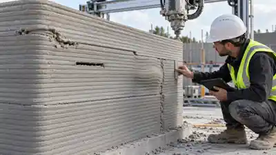
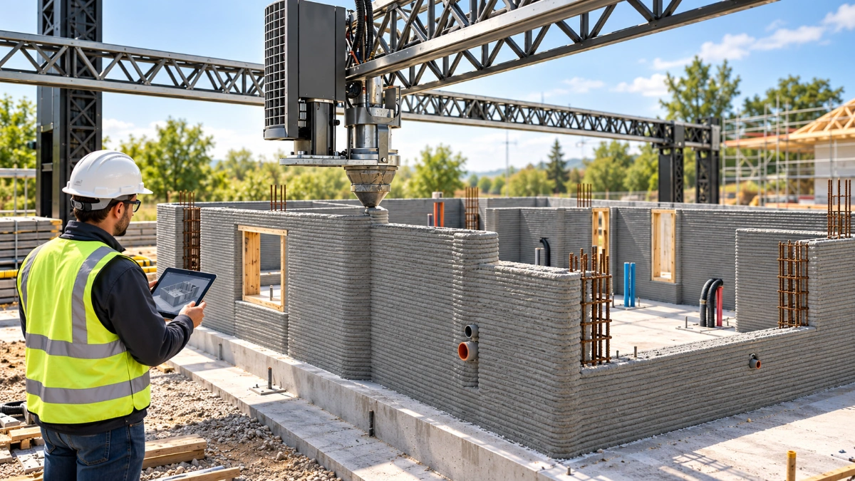
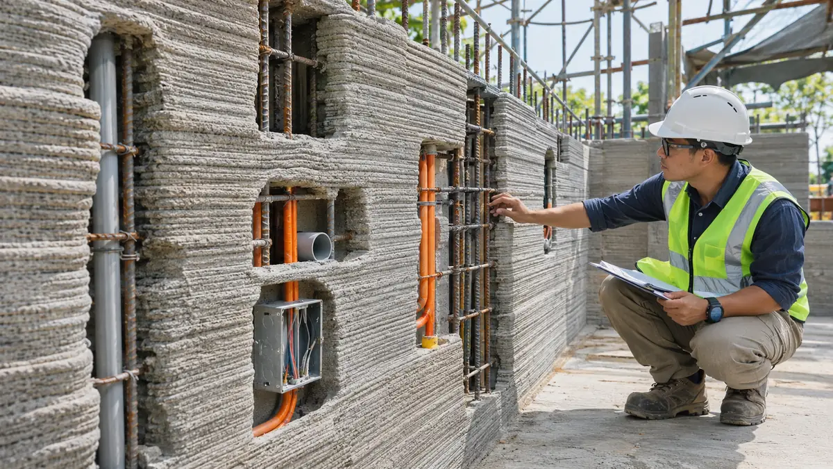
Inspector checks reinforcement and embedded conduits in a 3D printed concrete wall before concealment.

The checklist

Design and coordination

  1. Current approved reinforcement/MEP coordination drawings identify the elements to be inspected.
  2. The print file and intended layer/cavity arrangement accommodate the approved reinforcement and embeds.

Reinforcement and anchors

  1. Required reinforcing bars, anchors or connectors have the approved type, size and grade.
  2. Reinforcement positions, spacing, laps and cover/clearances satisfy the approved structural details.
  3. Starter bars, connection hardware and required supports are correctly located and secured.

Cavities and grout interfaces

  1. Required ducts and grout cavities remain accessible, unobstructed and dimensionally suitable.
  2. Any prescribed grout preparation/placement stage and inspection prerequisites are satisfied before covering.

MEP and openings

  1. Conduits, boxes, sleeves and penetrations are in the approved locations.
  2. Embedded services and supports do not conflict with reinforcement, structural connections or the print path.
  3. Required fire/water/air sealing and movement details are provided or identified for the correct follow-on stage.

Evidence and release

  1. Photos/measurements identify the wall, elevation or layer before the work is concealed.
  2. Critical deviations have been referred for designer/engineer disposition rather than field modification.
  3. Required pre-concealment hold/witness inspections and release authorization have been recorded.

Preview the printable checklist

Preview page one below. Open the image or download the PDF for all pages.
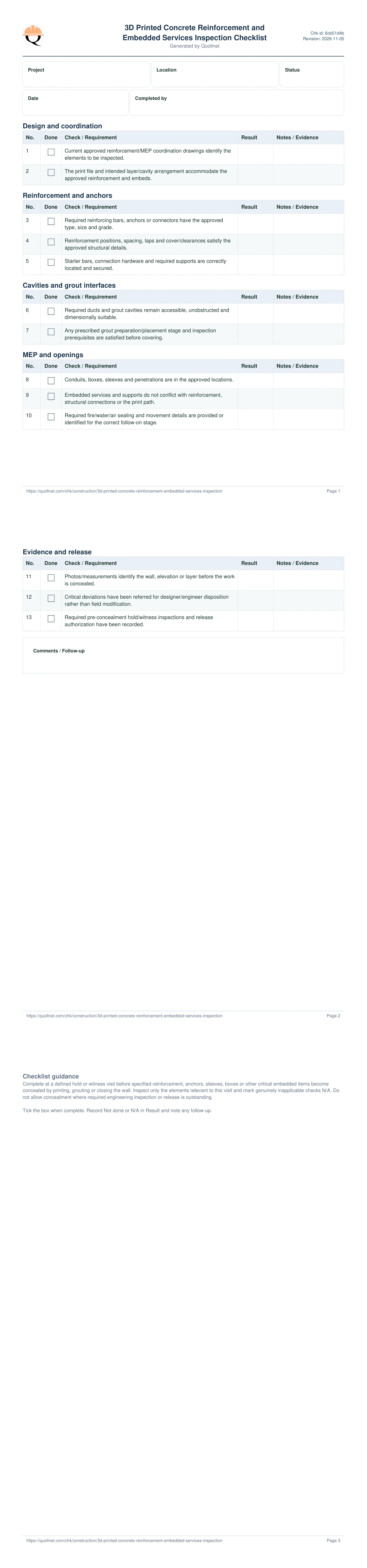
First-page preview of the 3D Printed Wall — Reinforcement & Embeds printable checklist template.
3D Printed Wall — Reinforcement & Embeds · Page 1 preview · Open image with all pages

At a glance

  • For a single pre-concealment inspection of reinforcement and embedded services in a printed wall.
  • Verify approved detail, position, stability, access, clearances and release evidence.
  • Structural and service acceptance depends on approved design details and project ITP.
Elie Saad's photo
Elie Saad
10704
132
23
29

Related Articles

Broader reading and guidance connected to this checklist topic.

3d Printed Concrete Qa/qc: Inspection, Process Control & Acceptance
3
en
3d Printed Concrete Qa/qc: Inspection, Process Control & Acceptance
EN
3d Printed Concrete Qa/qc: Inspection, Process Control & Acceptance

Practical QA/QC guide for 3D printed concrete walls: qualification, pre-print checks, live process control, interruptions, testing, defects and accept...

Article 2026-10-01
3d Printed Concrete Defects: Visual Field Guide For Site Engineers
3
en
3d Printed Concrete Defects: Visual Field Guide For Site Engineers
EN
3d Printed Concrete Defects: Visual Field Guide For Site Engineers

Visual field guide to 3D printed concrete defects: tearing, gaps, misalignment, slumping, restart interfaces, cracks, causes, records and escalation.

Article 2026-10-03
How 3d Printed Houses Are Built: What The Viral Videos Don’t Show You
H
en
How 3d Printed Houses Are Built: What The Viral Videos Don’t Show You
EN
How 3d Printed Houses Are Built: What The Viral Videos Don’t Show You

How 3D printed houses are really built: wall printing, reinforcement, MEP, QA/QC, standards, completion, cost and why printing time is not turnkey con...

Article 2026-09-27
Concrete Cube Vs Cylinder Strength: Why The 0.8 Rule Can Mislead
C
en
Concrete Cube Vs Cylinder Strength: Why The 0.8 Rule Can Mislead
EN
Concrete Cube Vs Cylinder Strength: Why The 0.8 Rule Can Mislead

Concrete cube vs cylinder strength explained: why geometry changes results, why 0.8/0.85 conversions can mislead, and how QA/QC should compare results...

Article 2026-09-11
Inspection & Test Plan (itp) In Construction — Complete Guide, Templates & Legal Essentials
I
en
Inspection & Test Plan (itp) In Construction — Complete Guide, Templates & Legal Essentials
EN
Inspection & Test Plan (itp) In Construction — Complete Guide, Templates & Legal Essentials

Learn how to write an ITP (Inspection & Test Plan) for construction—templates, hold/witness points, acceptance criteria, ISO 9001 alignment, and FIDIC...

Article 2026-05-29

Related Checklists

Keep the workflow moving with nearby templates chosen from similar checklist content.

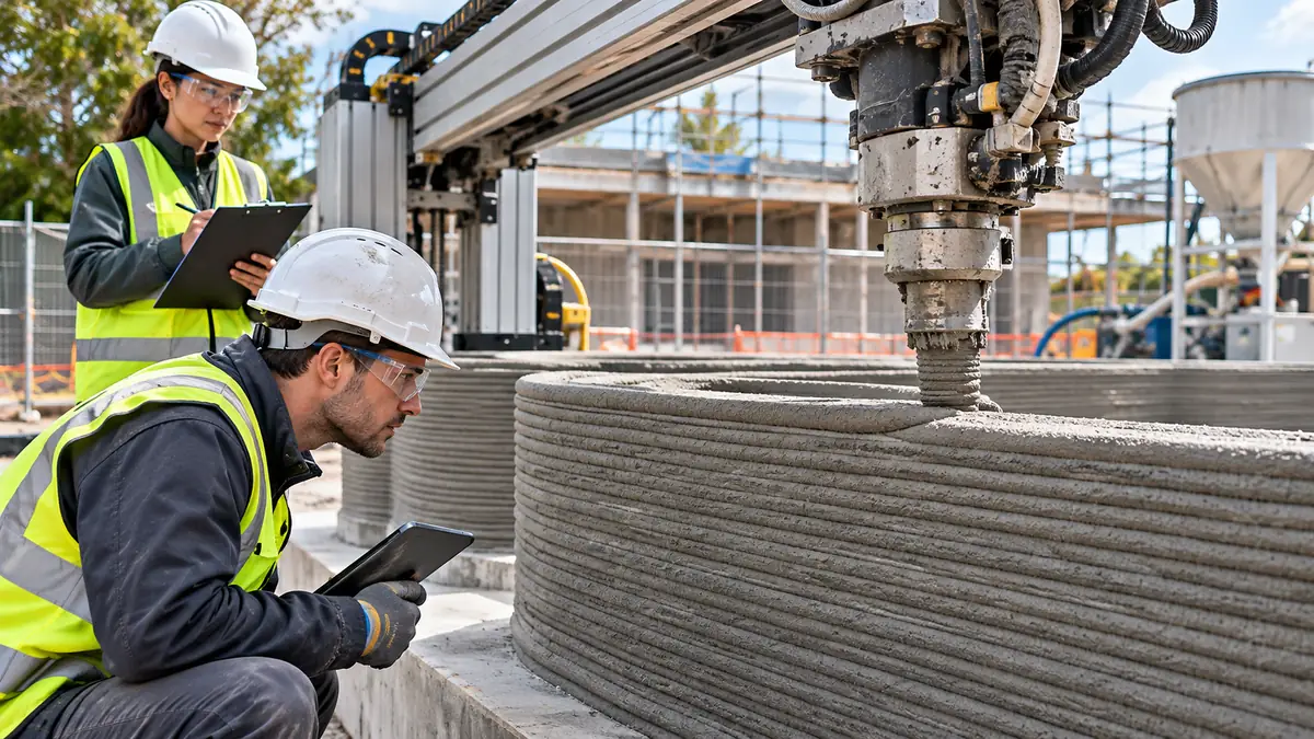
QA inspectors check the layers of a 3D concrete wall as a robotic printer deposits fresh concrete. image
3
construction
3D Concrete Printing During-Print Quality Inspection Checklist
Construction
3D Concrete Printing During-Print Quality Inspection Checklist

Complete this checklist for one defined observation visit during active printing of a wall or segment. Repeat the checklist for later visits. Record l...

Create a construction QA/QC checklist titled:
3D Printed Concrete Inspection Checklist — Before, During & After Printing
Purpose
Create a practical field inspection checklist for site engineers, QA/QC engineers, inspectors and 3D-concrete-printing contractors inspecting extrusion-based 3D printed concrete walls.
The checklist must be usable during an actual print and should generate a professional supporting article explaining how to use it.
Important technical principle
3D printed concrete inspection must control both:
1. the finished wall, and
2. the printing process that produced it.
The checklist should therefore preserve evidence of:
- what was printed;
- which approved digital/model/print-file revision was used;
- which material batch was used;
- how the printer was configured;
- what happened during printing;
- interruptions and restart conditions;
- reinforcement and embeds;
- final geometry;
- defects;
- curing;
- specimens/testing; and
- final disposition/release.
Do not invent universal tolerances
Do not state generic millimetre limits, bead-offset percentages, maximum layer intervals or other numerical acceptance limits unless they are clearly identified as project/system-specific examples.
Acceptance must normally refer to:
- approved project specification;
- approved drawings/model;
- qualified printing system;
- approved method/procedure;
- Inspection and Test Plan (ITP);
- manufacturer/system requirements;
- structural design requirements; and
- applicable codes/standards.
Where a value is project-specific, provide a field such as:
Acceptance / Reference: __________
or
Specified value: ________
Terminology
Use Print File / Toolpath Revision, not only “G-code,” because not every printer exposes G-code.
Use:
- Hold
- Witness
- Surveillance
where appropriate.
Every inspection item should allow:
- Pass
- Fail
- N/A
- Recorded value / observation
- Evidence / photo reference
- Action / NCR / observation reference where relevant
Checklist structure
Header / traceability
Capture:
- Project
- Location
- Wall / Print Segment ID
- Grid / Element reference
- Inspection date and time
- WIR / Inspection reference
- Approved drawing/model revision
- Print file/toolpath revision
- Printer ID
- Nozzle/configuration ID if applicable
- Approved mix/material ID
- Batch/lot ID
- Operator
- Contractor representative
- QA/QC inspector
PHASE 1 — BEFORE PRINTING / PRE-PRINT RELEASE
Include inspection items for:
Document and digital control
- Approved drawing/model revision
- Approved print file/toolpath revision
- Wall geometry, cavities and openings
- Required reinforcement and embeds
- Approved method statement/procedure
- Applicable ITP inspection point
Survey and substrate
- Wall centreline / coordinates
- Corners and openings
- Foundation/substrate level
- Starting surface condition
- Starter bars/dowels/anchors
Printer setup and calibration
- Printer zero/reference point
- Coordinate-system alignment
- Printer level/setup
- Working envelope
- Motion path
- Collision clearance
- Calibration/verification status
Material traceability and readiness
- Approved mix/material ID
- Batch/lot
- Mixing/batching time
- Accelerator/admixture dosage where relevant
- Material within approved printing/open-time window
- Printability requirements satisfied
Do not imply that conventional slump alone establishes printability.
Reinforcement, embeds and MEP
- Vertical reinforcement
- Horizontal reinforcement/ties where relevant
- Anchors
- Sleeves
- Service ducts
- Electrical boxes
- Inserts
- Openings
- Items that will become inaccessible during printing
Environmental conditions
Record:
- Ambient temperature
- Relative humidity
- Wind
- Direct solar exposure
- Rain/weather risk
- Required protection against drying/skinning
Pre-print release
Include a clear:
READY TO PRINT / HOLD
decision.
PHASE 2 — DURING PRINTING / LIVE PROCESS CONTROL
Include:
Extrusion continuity
Inspect for:
- continuous flow;
- under-extrusion;
- over-extrusion;
- tearing;
- gaps;
- pump pulsation;
- nozzle blockage.
Bead and layer geometry
Record where required:
- bead width;
- layer height;
- wall thickness;
- cavity/shell dimensions.
Compare against the approved system requirements rather than inventing universal limits.
Layer alignment
Monitor:
- lateral offset;
- face alignment;
- corners/curves;
- cumulative dimensional drift.
Buildability
Inspect lower layers for:
- spreading;
- slumping;
- bulging;
- leaning;
- buckling;
- progressive deformation;
- local instability/collapse.
Nozzle clearance and contact
Check for:
- nozzle drag;
- collision;
- scraping of earlier layers;
- disturbance of reinforcement/embeds;
- changes in nozzle-to-wall clearance.
Note that nozzle contact can disturb still-fresh underlying layers and may affect interlayer contact beyond the visibly damaged surface.
Layer interval / timing
Record:
- relevant layer interval;
- planned pauses;
- unplanned pauses;
- comparison with approved maximum interval/restart procedure.
Do not use a universal “cold joint” limit.
Reinforcement and embeds installed during printing
Verify before concealment:
- horizontal ties;
- reinforcement;
- mesh;
- anchors;
- sleeves;
- service inserts;
- insulation if applicable.
Live defect monitoring
Include recognition of:
- tearing;
- under/over-extrusion;
- gaps;
- misalignment;
- slumping/bulging;
- nozzle damage;
- voids;
- poor layer contact;
- cracking;
- dimensional drift.
PRINT INTERRUPTION / RESTART RECORD
Make this a prominent dedicated subsection.
Record:
- wall/segment;
- layer/elevation;
- stop time;
- restart time;
- total downtime;
- reason;
- material batch before stop;
- material batch after restart;
- environmental conditions;
- exposed-layer condition;
- cleaning or surface preparation;
- additional material/treatment used;
- inspection before restart;
- approval/disposition;
- approved by.
MANDATORY STOP / HOLD CONDITIONS
Create a clearly visible warning section.
Examples of conditions requiring stop, hold or immediate technical review should include:
- physical wall location does not match digital/model coordinates;
- wrong print revision;
- missing structural reinforcement, anchor or critical embed;
- progressive bulging/buckling/instability;
- partial collapse;
- major extrusion discontinuity;
- significant nozzle collision;
- wall geometry progressively moving outside the approved envelope;
- interruption exceeding the approved restart/process limit;
- visible layer separation/delamination;
- any condition where continuing would conceal or worsen a nonconformance.
Distinguish between:
Immediate stop
and
Hold for engineering / QA disposition
where appropriate.
PHASE 3 — AFTER PRINTING / FINAL INSPECTION
As-built geometry
Check:
- wall location;
- wall length;
- total height;
- wall thickness;
- plumbness;
- straightness/alignment;
- openings;
- corners;
- connection zones;
- cavity dimensions where applicable.
Record survey/as-built reference.
Visual defects
Inspect for:
- tearing;
- gaps/voids;
- layer separation;
- restart interfaces;
- cracks;
- local deformation;
- exposed reinforcement;
- damaged surfaces;
- dimensional abnormalities.
Reinforcement / embeds / openings
Verify final position and presence of accessible:
- reinforcement;
- anchors;
- sleeves;
- penetrations;
- inserts;
- openings.
Curing and protection
Verify:
- approved curing method;
- start time;
- protection from drying;
- thermal/weather protection;
- protection from physical damage.
Test specimens and companion printed elements
Record:
- specimen IDs;
- companion wall/panel IDs;
- material batch link;
- scheduled test age(s);
- required test reference.
Do not hard-code 7- and 28-day testing as universal.
Cavity grouting / structural infill
Include only if applicable:
- cavity cleanliness;
- reinforcement;
- seals/formwork;
- readiness for grout/infill;
- release status.
Final release
Include:
- Accepted
- Accepted with comments / conditional
- Hold
- Rejected / NCR
and signatures/approval fields as appropriate.
DEFECT / DEVIATION LOG
Include a small structured register with:
- Location / layer / elevation
- Defect or deviation
- Photo/evidence reference
- Observation / NCR reference
- Engineering disposition
- Repair action
- Reinspection status
- Closure reference
Supporting article
Generate a supporting article explaining:
3D Printed Concrete Inspection Checklist: Before, During & After Printing
The article should:
- explain why inspection of 3D printed concrete differs from conventional concrete;
- explain that process history is part of the quality evidence;
- explain Hold / Witness / Surveillance points;
- explain the before/during/after workflow;
- explain why print interruptions need a dedicated record;
- explain that visible defects are not automatically structural failures;
- explain when printing should be stopped;
- explain that project/system-specific tolerances govern acceptance;
- explain that the normal project WIR can be used for inspection of printed work;
- mention that an NCR should be raised when a defined requirement has actually been breached;
- clearly state that the checklist is a practical project template and not a substitute for the approved ITP, structural design, qualified printing system or project specification.
Reference framework
Use current authoritative sources where applicable, particularly:
- ICC 1150-2026 — Standard for Automated Construction Technology for 3D Printing Walls
- ISO/ASTM 52939:2023 — Additive manufacturing for construction — Qualification principles
- relevant NIST additive construction / cement-based additive manufacturing research
Do not invent requirements that these sources do not contain.
Output / usability
The checklist should work well as:
- an interactive QChecklist;
- a printable PDF;
- an editable/exportable Excel record.
Keep field text concise enough for actual site use. Avoid long explanatory paragraphs inside checklist rows. Put explanations in the supporting article instead.
The final checklist should feel like a real QA/QC inspection record, not a blog summary. image
3
construction
3D Printed Concrete Inspection Checklist: Before, During, After
Construction
3D Printed Concrete Inspection Checklist: Before, During, After

3D Printed Concrete Inspection Checklist — Before, During & After Printing is a practical, field-ready QA/QC tool for extrusion-based 3D concrete prin...

Basement Wall Reinforcement and Embeds (Vertical) Inspection image
B
construction
Basement Wall Reinforcement and Embeds (Vertical) Inspection
Construction
Basement Wall Reinforcement and Embeds (Vertical) Inspection

Basement Wall Reinforcement and Embeds (Vertical) Inspection focuses on confirming vertical reinforcement, embedded items, openings, and sleeves are c...

Inspect basement wall formwork and ties (vertical) image
B
construction
Inspect basement wall formwork and ties (vertical)
Construction
Inspect basement wall formwork and ties (vertical)

Inspect basement wall formwork and ties (vertical) is a targeted pre-pour procedure that focuses on vertical wall formwork alignment, dimensions, and ...

Inspect Curtain Wall Perimeter Firestopping Pre-Concealment image
C
construction
Inspect Curtain Wall Perimeter Firestopping Pre-Concealment
Construction
Inspect Curtain Wall Perimeter Firestopping Pre-Concealment

Inspect curtain wall perimeter firestopping before concealment is a critical hold-point that confirms the perimeter joint fire barrier is correctly in...