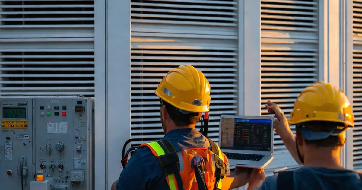
Test dynamic façade manual override and emergency stop functionality for commissioning teams and facility operators, confirming local bypass, fail-safe stops, and BMS isolation with timed responses, electrical readings, and tamper-proof evidence capture.
- Clarifies prerequisites, lockout boundaries, and stakeholder notifications before testing.
- Validates local override stations and actuator behavior within defined response times.
- Confirms emergency stop circuits isolate power and motion safely and reliably.
- Interactive, commentable, export, QR code for authenticated records.
The checklist
Pre-Test Safety and Notifications
- Issue permit-to-work and notify affected occupants and security; record distribution list. Acceptance: acknowledgments logged before start. Evidence: PTW number, email/notice screenshots, supervisor signature.
- Establish a 2 m exclusion zone around moving façade elements using barriers and signage. Acceptance: no public access observed. Evidence: photos showing barriers and measured distance.
- Conduct toolbox talk on pinch, shear, and fall hazards; define roles and stop authority. Acceptance: attendance sheet signed. Evidence: signed briefing record and photo of posted emergency contacts.
- Verify lockout/tagout for adjacent non-test circuits; confirm controlled energization for test circuits. Tools: lockout kit, voltage tester. Acceptance: correct tags applied, test circuits safe to energize. Evidence: photos and tester readings.
Power and Control Setup
- Measure supply at actuator control panel L-N and L-PE with a calibrated multimeter. Acceptance: within design voltage ±5%. Evidence: photo of meter display and panel ID label.
- Confirm BMS/fieldbus handover set to Local at the controller/key-switch. Acceptance: local mode indicator illuminated; remote commands disabled. Evidence: controller LED photo and BMS screenshot.
- Inspect emergency stop circuit continuity de-energized using a continuity tester. Acceptance: loop resistance < 1 Ω; correct wiring order. Evidence: tester reading photo and marked schematic.
- Check labeling of local override switch and E-stop: device tag, direction arrows, and zone ID. Acceptance: legible from 1 m. Evidence: close-up photos of labels.
Manual Override Testing
- Switch controller to Local/Manual with authorized key; remove key after selection. Acceptance: status LED shows Local; key control logged. Evidence: photo of selector position and key ID.
- Command OPEN via local switch; time full travel with a stopwatch. Acceptance: completes within design time ±10%, no judder or alarms. Evidence: recorded time, video of travel, and end-limit indicator photo.
- While moving, press STOP/HOLD to arrest motion mid-travel. Acceptance: motion ceases within 1 s; position holds without drift for 60 s. Evidence: timed video and position photo.
- Command CLOSE to end-stop; verify limit switch activation and motor cut-off. Acceptance: stop at closed limit; no overrun or back-drive. Evidence: limit LED/photo and stopwatch reading.
- Simulate loss of power using a test isolation switch while motion is active. Acceptance: movement stops within 1 s; brakes hold position; no uncontrolled drop. Evidence: video, breaker/switch ID, and meter shows 0 V at drive.
- Restore power and observe system state. Acceptance: no unintended movement on re-energization; controller reports ready. Evidence: video of recovery and controller status photo.
Emergency Stop Testing
- Initiate motion, then press nearest E-stop. Measure time to de-energize drive contactor using stopwatch and voltage probe. Acceptance: 0 V at drive within 1 s. Evidence: video and meter photo.
- Verify all grouped façade actuators in the defined zone halt simultaneously. Acceptance: no residual motion across the zone within 1 s. Evidence: wide-angle video of elevation.
- Attempt restart with local switch while E-stop remains latched. Acceptance: restart inhibited; drives stay de-energized. Evidence: video and 0 V verification at drive terminals.
- Reset E-stop per manufacturer (twist/pull), then re-arm circuits. Acceptance: normal control restored only after deliberate reset and acknowledgment. Evidence: photo of reset action and controller status.
System Response and Reset
- Check alarm/event logs for E-stop activation, power-loss, and resets with timestamps and device IDs. Acceptance: entries created within 10 s. Evidence: BMS/PLC screenshots.
- Inspect motor protection (thermal/overload) and drive fault LEDs. Acceptance: no faults latched post-tests. Evidence: panel interior photos showing indicators normal.
- Return controller to Auto/Remote; confirm BMS control resumes with a supervised command. Acceptance: remote command accepted; local disabled. Evidence: BMS command log and selector position photo.
- Compile evidence pack: photos, videos, readings, calibration certificates, and signatures. Acceptance: files named with location and ISO date; uploaded to CDE. Evidence: upload receipt and index list.
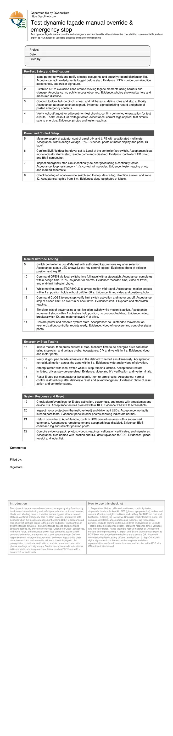
Preview the printable checklist
Preview page one below. Open the image or download the PDF for all pages.
At a glance
- Reduce risk by proving local manual override works independently of BMS and network controls. Measure travel times, verify limit-switch changes, and capture photos and multimeter readings. Prevent unintended movement, equipment damage, and occupant disruption with clear acceptance thresholds and documented evidence.
- Validate emergency stop performance by demonstrating power removal to drives within 1 second during motion, system-wide halt across grouped façades, and restart inhibition while E-stop remains latched. Confirm proper reset, alarms, and event logging, securing a dependable fail-safe that operators can trust.
- Interactive online checklist with tick, comment, and export features secured by QR code.
- Accelerate handover with a structured test record: timestamps, device IDs, voltages, travel times, photos, signatures, and calibration certificates. Export a clean PDF/Excel pack for review and archive, supporting warranty activation and ongoing operations training with reliable, searchable data.
How to Use the Interactive Test Checklist
- Preparation: Gather calibrated multimeter, continuity tester, stopwatch, barriers, lockout kit, PPE (gloves, eye protection), radios, and camera. Confirm daylight conditions and staffing. Set BMS to Local and brief roles.
- Using the Interactive Checklist: Start interactive mode, tick items as completed, attach photos and readings, tag responsible persons, and add comments for punch items or deviations.
- Execute Tests: Follow the sequence exactly, capturing response times, voltages, and indicator states. Pause testing to resolve hazards or unexpected motions before proceeding.
- Export and Share: Generate an export as PDF/Excel with embedded media links and a secure QR. Share with commissioning leads, safety officers, and facilities.
- Sign-Off: Collect digital signatures from the responsible engineer and client representative, confirm document version, and archive in the CDE with QR-authenticated record.
Safety-first setup and boundaries before testing
Pre-test preparation defines safe boundaries and communication lines. Establish a 2 m exclusion zone around moving façade elements and brief all roles on stop authority and radio channels. Confirm that adjacent systems are safely locked out and that test circuits are energized only under control of the commissioning lead. Verify supply voltage with a calibrated multimeter and label all local controls and emergency stops clearly at eye level. Ensure the building management system (BMS) is set to Local or bypassed as required so remote signals cannot interfere with the test sequence. Document all notifications to occupants and security to avoid nuisance alarms or unexpected blinds movement during daylight hours. Finalize a rescue plan for stuck or partially deployed elements, including manual crank access if provided. These precautions prevent entrapment, glass damage, and panic triggers while enabling clean, measurable results.
- Define and barrier a 2 m exclusion zone.
- Brief roles, hazards, and stop authority in writing.
- Verify supply voltage with a calibrated multimeter.
- Set BMS to Local; disable remote interference.
- Label local controls and E-stops clearly.
Proving manual override behavior under realistic conditions
Manual override validation demonstrates that local stations can safely open, stop, and close dynamic façade actuators without BMS. Use a key-switch to select Local, then time full-travel OPEN and CLOSE runs with a stopwatch, comparing results against design values within ±10%. During movement, use STOP/HOLD to arrest motion and confirm the element holds position for at least 60 s without drift. Simulate a controlled power-loss with a test isolation switch; verify that brakes engage, drives de-energize, and no uncontrolled descent occurs. Inspect limit-switch and controller indicators to confirm end-of-travel logic cuts power. Record videos, travel times, and limit LED states to build objective evidence. This testing ensures occupants can be protected during BMS outages or network faults and that maintenance teams can position façades safely for cleaning.
- Select Local with an authorized key-switch.
- Time travel; accept within design ±10%.
- Stop mid-travel; hold for at least 60 s.
- Simulate power loss; verify no uncontrolled drop.
- Capture videos and limit indicator photos.
Emergency stop performance, reset logic, and documentation
Emergency stop (E-stop) testing proves fail-safe isolation and restart inhibition. While an actuator is moving, hit the nearest E-stop and measure the time to achieve 0 V at the drive terminals; acceptance is within 1 s. Confirm all grouped façades in the zone halt simultaneously with no residual creep. Attempt a restart with E-stop latched to verify commands are inhibited. Reset the E-stop per manufacturer instructions and ensure normal control only returns after a deliberate reset and acknowledgment. Finally, confirm alarms and event logs capture device IDs and timestamps within 10 s, then compile evidence—photos, videos, voltages, and signatures—into a named archive. Proper documentation supports warranty activation, training, and future incident reviews.
- Verify 0 V at drive within 1 s.
- Check zone-wide halt without creep.
- Restart inhibited while E-stop latched.
- Confirm logs with IDs and timestamps.
- Archive a complete evidence package.