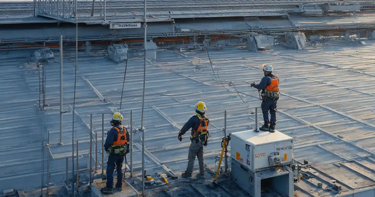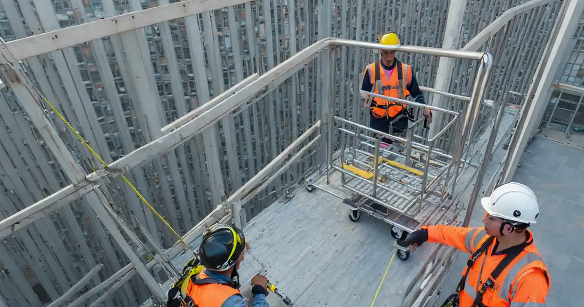
Test façade maintenance access rails and traveler systems before handover ensures safe, compliant operation of BMU rails and traveling cradles for facility owners and contractors.
- Pre-handover inspection, functional checks, proof loading, and documentation.
- Prevent derailment, falls, electrical faults, and warranty disputes.
- Calibrated tools, measurable tolerances, photo/video evidence, third-party witnessing.
- Interactive, commentable, export-ready checklist secured by QR code.
The checklist
Pre-Test Documentation & Safety Controls
- Confirm approved method statement, risk assessment, and rescue plan on-site; verify latest drawings and manufacturer manuals are AFC. Acceptance: all documents approved per project/authority; Evidence: photos of stamps/revisions and sign-offs.
- Establish 2 m exclusion zones at roof edge and below façade; install barriers and warning signage. Acceptance: continuous perimeter with no unauthorized entry; Evidence: area photos and permit-to-work record.
- Check PPE for all involved (full-body harness, double lanyard, helmets, gloves); record harness serials and inspection dates. Acceptance: within service life, no damage; Evidence: serial log and photos.
- Conduct toolbox talk covering hazards, communication protocol, and emergency roles; test radios. Acceptance: 100% attendance; Evidence: signed briefing sheet and time-stamped radio test record.
Rail System Inspection & Tests
- Visually inspect rails, joints/splices, brackets, and welds using flashlight and mirror; mark defects. Acceptance: no visible cracks, deformation, or coating damage exposing base metal; Evidence: annotated photos.
- Measure rail straightness and level using laser line and digital level. Acceptance: deviation ≤ 3 mm over 10 m and level within ±1 mm/m, or per approved specifications; Evidence: recorded readings and layout sketch.
- Torque-check rail brackets/anchors with a calibrated torque wrench. Acceptance: within design torque ±10% (per manufacturer/project); Evidence: torque log with values and wrench calibration certificate.
- Proof-load selected rail brackets/anchors with a hydraulic tester. Acceptance: apply specified proof load (e.g., 1.25× service) for 60 s; displacement ≤ 2 mm; Evidence: gauge photo and displacement reading.
Traveler/Cradle Mechanical & Functional Tests
- Inspect traveler trolley wheels, flanges, and bearings; check lubrication. Acceptance: no flat spots; diameter variance ≤ 1 mm across wheels; free spin ≥ 10 s; Evidence: photos and measurements.
- Verify end stops/buffers installed and secure; measure clearance to rail ends. Acceptance: end-of-travel switch/stop engages ≥ 150 mm before rail end; Evidence: close-up photos and measurements.
- Run traveler full rail length at low and rated speeds without load. Acceptance: no binding/derailment; travel time for 50 m within ±10% of rated; Evidence: video and time log.
- Test parking/service brakes with cradle at mid-span and 100% WLL suspended. Acceptance: no creep > 5 mm over 5 min; Evidence: time-lapse or video and measurement photo.
Electrical & Control System Tests
- Perform insulation resistance test on motors and control circuits with a 500 V DC megohmmeter. Acceptance: ≥ 1 MΩ or per manufacturer; Evidence: megger readings and calibration certificate.
- Verify earth continuity from traveler/cradle frame to building earth using an earth tester. Acceptance: ≤ 0.5 Ω (or project requirement); Evidence: test reading and photo of connection point.
- Test emergency stop, limit switches, and interlocks including end-travel and tilt sensors. Acceptance: motion cut-off < 1 s; switches actuate before physical end stop; Evidence: test log and photos.
- Check control pendant/remote: deadman operation, correct direction labeling, and enclosure IP integrity. Acceptance: no unintended motion; labels legible; enclosure undamaged; Evidence: photos and functional tick sheet.
Load & Rescue Testing
- Static load test using calibrated water bags/dynamometer to 125% WLL on mid-span. Acceptance: hold 10 min with no permanent deformation; rail deflection within manufacturer limit; Evidence: load curve and deflection gauge photos.
- Dynamic function test at rated load: 10 start/stop cycles and full-length traverse. Acceptance: smooth motion; overspeed trip verified; surface temperatures ≤ 60 °C; Evidence: cycle log and IR thermometer readings.
- Proof-load traveler tie-off/fall-arrest points per manufacturer using a calibrated rig. Acceptance: hold specified load (e.g., 12 kN for 3 min); residual displacement ≤ 1 mm; Evidence: test report and photos.
- Conduct rescue drill simulating incapacitated operator from mid-span to safe zone. Acceptance: completed within 15 min with correct devices; Evidence: video, attendance sheet, and signed drill evaluation.
Handover Documentation & Tagging
- Affix durable asset tags on rails and traveler stating WLL, serials, test date, and next due. Acceptance: labels legible and secured; Evidence: close-up photos.
- Compile and upload O&M pack: as-builts, manuals, commissioning forms, test certificates, and calibration records. Acceptance: complete index verified; Evidence: digital link and approval signature.
- Deliver operator training on normal/emergency operation and daily checks; assess competence. Acceptance: minimum two trained operators; assessment score ≥ 80%; Evidence: attendance and assessment records.
- Generate QR code linking to this checklist and manuals; verify scan at access points; obtain final sign-offs. Acceptance: QR functional; client/contractor/inspector signatures captured; Evidence: QR screenshots and signed certificates.
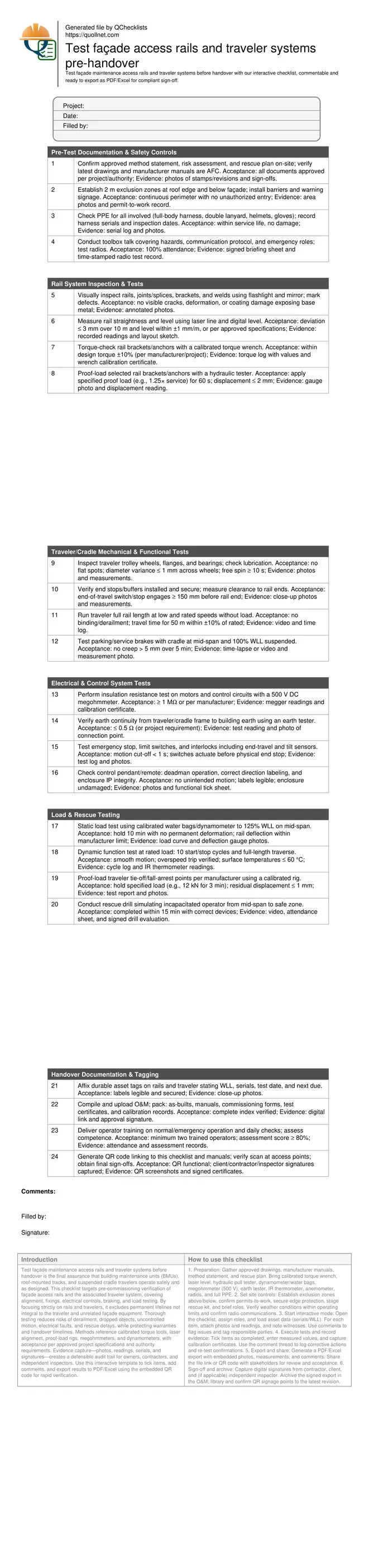
Preview the printable checklist
Preview page one below. Open the image or download the PDF for all pages.
At a glance
- Validate BMU rails and traveler systems with measurable criteria: alignment, torque, proof loads, insulation resistance, and brakes. Prevent post-handover defects by capturing photos, readings, serial numbers, and signatures, ensuring traceable compliance with approved specifications and authority requirements before operations begin.
- Reduce site risk through structured sequencing: documentation and exclusion zones first, then mechanical and electrical checks, followed by static/dynamic load tests and a timed rescue drill. Each step defines tools, tolerances, and acceptance cues to deliver safe, reliable façade access from day one.
- Streamline handover with complete O&M deliverables: approved drawings, commissioning forms, calibration certificates, training records, asset labels, and QR-linked manuals. Digital evidence accelerates stakeholder sign-off, minimizes punch list disputes, and supports future maintenance and statutory re-testing without repeating baseline investigations.
- Interactive online checklist with tick, comment, and export features secured by QR code.
How to Use This Pre-Handover Testing Checklist
- Preparation: Gather approved drawings, manufacturer manuals, method statement, and rescue plan. Bring calibrated torque wrench, laser level, hydraulic pull tester, dynamometer/water bags, megohmmeter (500 V), earth tester, IR thermometer, anemometer, radios, and full PPE.
- Set site controls: Establish exclusion zones above/below, confirm permits-to-work, secure edge protection, stage rescue kit, and brief roles. Verify weather conditions within operating limits and confirm radio communications.
- Start interactive mode: Open the checklist, assign roles, and load asset data (serials/WLL). For each item, attach photos and readings, and note witnesses. Use comments to flag issues and tag responsible parties.
- Execute tests and record evidence: Tick items as completed, enter measured values, and capture calibration certificates. Use the comment thread to log corrective actions and re-test confirmations.
- Export and share: Generate a PDF/Excel export with embedded photos, measurements, and comments. Share the file link or QR code with stakeholders for review and acceptance.
- Sign-off and archive: Capture digital signatures from contractor, client, and (if applicable) independent inspector. Archive the signed export in the O&M library and confirm QR signage points to the latest revision.
Why pre-handover testing of rails and travelers matters
Façade access rails and traveler systems demand rigorous pre-handover testing because they combine structural, mechanical, and electrical risks at height. This stage validates that rails are aligned, fixings torqued, and traveler motion and braking are reliable before routine maintenance begins. Without it, the likelihood of derailment, dropped loads, electrical faults, or failed rescues increases, exposing people and property to harm and delaying occupancy. Practical verification uses calibrated torque wrenches, laser levels, hydraulic proof-load equipment, and dynamometers, with acceptance aligned to manufacturer data and per approved project specifications and authority requirements. Evidence—photos, readings, and signatures—creates an auditable record that supports warranty claims and future re-certification. Typical jobsite sequencing starts with documentation and exclusion zones, proceeds to rail and trolley inspection, then executes electrical tests and load-based functional trials, finishing with training and sign-off.
- Sequence tests from paperwork to load to sign-off.
- Use only in-date, calibrated instruments and record certificates.
- Capture defects with annotated photos and exact locations.
- Apply acceptance per manufacturer and approved specifications.
Methods, tolerances, and acceptance cues in practice
On the roof, a laser line and digital level quickly confirm rail straightness and slope within agreed tolerances, while torque logs show anchors meet design values. Hydraulic testers proof-load select brackets with displacement monitoring to flag creep or movement. Traveler checks verify wheel condition, end stops, and brakes, then traverse tests confirm smooth, derailment-free motion. Electrically, megger readings must meet minimum insulation thresholds, and ground continuity must be low and stable. Static and dynamic load tests with water bags or calibrated weights validate structure and drive systems under real conditions. Finally, a timed rescue drill demonstrates workable emergency procedures. Throughout, acceptance values follow manufacturer data and the project’s approvals; where tolerances differ, the stricter requirement governs. Clear, dated evidence and witnesses help resolve disputes at handover.
- Record actual readings; avoid pass/fail without numbers.
- Hold proof loads long enough to detect creep or slip.
- Test end switches before contacting hard end stops.
- Time and video critical functional and rescue steps.
Documentation, traceability, and digital sign-off
Testing is only as strong as the traceability behind it. Maintain a complete O&M pack with approved drawings, commissioning forms, test certificates, and calibration records linked directly to each asset’s serial number. Use QR codes at access points to open the latest interactive checklist and manuals. During testing, attach photos, megger prints, torque logs, and dynamometer traces to the exact checklist item, tagging location and time. Close out comments with corrective actions and re-test evidence. Upon completion, export the results as PDF/Excel and secure final digital signatures from the contractor, client, and (where required) an independent inspector. This reduces punch list churn, compresses handover time, and establishes a reliable baseline for future periodic inspections and statutory re-certification.
- Link evidence to specific asset IDs and locations.
- Use QR codes to prevent outdated documents in the field.
- Export signed records to PDF/Excel for archiving.
- Retain calibration certificates with each instrument log.