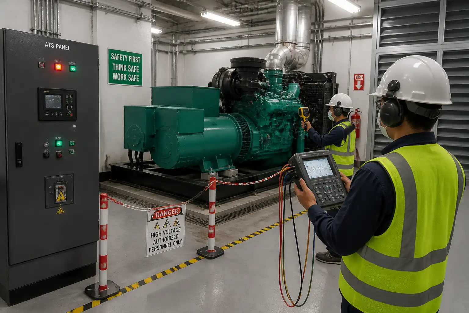

Method Statement: Integrated Testing of Generator, Automatic Transfer Switch (ATS), and Essential Loads – Method Statement
AI-assisted method statement with matching ITP, PDF download, and Excel export.
More than a static template
Unlike a downloadable Word or PDF template, this method statement is an AI-assisted editable starting point connected directly to a matching Inspection and Test Plan. Every section is structured, project-adaptable, and ready to export.
- AI-assisted drafting — Customize every section with AI for your specific project scope.
- Linked ITP — A matching inspection and test plan is generated alongside the method statement.
- Multiple export formats — Download as a formatted PDF or editable Excel spreadsheet.
- Editable starting point, not a final document — Review, verify, and adjust all content against your project requirements before use.
Static template vs. Quollnet workflow
| Feature | Static template | Quollnet |
|---|---|---|
| Project-specific content | Manual fill-in required | AI-assisted customization |
| Linked ITP | Separate document, no link | Matching ITP included |
| Export formats | Usually PDF only | PDF and Excel |
| Structured sections | Free-form layout | 13 standardized sections |
| Saved to your account | Local file only | Cloud-saved, reusable |
| Content accuracy | You verify everything | AI-assisted, you still verify |
| Cost | Often free but time-intensive | Free to customize and download |
What you can customize
When you save this method statement to your account, every section becomes editable. The following 13 sections are included:
- Scope — Defines the activity and its boundaries.
- References — Standards, specifications, and drawings.
- Responsibilities — Roles and accountabilities.
- Resources — Labour, plant, and equipment summary.
- Materials — Materials and compliance requirements.
- Equipment — Tools and equipment details.
- Prerequisites — Hold points and pre-conditions.
- Method sequence — Step-by-step construction sequence.
- Safety controls — HSE risk controls and PPE.
- Environmental controls — Environmental mitigation measures.
- QA/QC — Quality inspection and test requirements.
- ITP — Inspection and Test Plan table (has its own page).
- Attachments — Referenced drawings and documentation.
Why this method statement is used
This method statement is used to define and communicate the approved procedure for carrying out method statement: integrated testing of generator, automatic transfer switch (ats), and essential loads on site. It ensures the work is planned in advance, the correct resources and controls are in place, and all personnel understand responsibilities, sequence, quality requirements, and safety controls before work begins. It aligns site execution with the documented scope and acceptance expectations.
Who uses this method statement
This method statement is used by contractors, site supervisors, project engineers, QA/QC engineers, HSE officers, consultants, and client representatives. It serves as a shared reference for planning, execution, supervision, inspection, and approval of the activity on site.
When it is prepared and submitted
The method statement is prepared before the work activity starts and submitted as part of the pre-construction documentation package for review and approval.
Who reviews or approves it
The method statement is usually submitted to the client representative, consultant, resident engineer, or project management consultant for review and approval before the work commences.
Important approval note
This method statement is an AI-assisted editable starting point, not a pre-approved document. Before use on any project, all content must be reviewed and approved by the relevant parties (superintendent, principal contractor, or client representative) in accordance with your contract and project quality plan.
For example: if your specification requires a departure from a referenced standard, that departure must be documented and approved separately — this method statement will not capture that automatically. Always verify against your applicable drawings, specifications, and regulatory requirements.
Method statement content
Scope
Purpose
This method statement defines the procedures, responsibilities, QA/QC controls, and HSE measures for integrated testing of the standby generator, ATS, and essential load systems. It includes mains failure simulation, automatic transfer, generator start and stabilization, load pickup and step-load testing, alarms/trips, return to normal supply (retransfer), documentation, and witness testing.
System Elements Covered
- Engine-generator set (diesel/gas) including governor, AVR, control panel, circuit breaker, and auxiliaries (starting system, battery charger, jacket water heaters, fuel/ventilation systems).
- Automatic Transfer Switch(es) (ATS) or Static Transfer Switches (where applicable), including bypass-isolation features if provided.
- Essential/Emergency distribution boards and connected critical equipment (e.g., life-safety, IT, medical, process). Fire pump and certain life-safety circuits may be tested via interface verification only per code/OEM. [Verify per project specifications]
- Monitoring and integration: BMS/SCADA, annunciators, remote alarms, and metering.
Objectives
- Demonstrate correct automatic operation upon mains failure and restoration.
- Verify generator performance (voltage, frequency, stability, THD, step-load behavior) under representative load.
- Verify ATS functionality, timing, and interlocks (open or closed transition as designed).
- Confirm correct operation of essential equipment on generator supply, including start/stop interlocks and alarms.
- Record performance data and produce final test reports and as-commissioned settings.
Exclusions/Clarifications
- Load-bank connection points outside generator system scope if not provided in contract.
- Protection coordination study and relay setting development are by design engineer; this method verifies implemented settings and basic trip operations.
- Fire pump functional full-flow testing is under separate method per NFPA 20/BS EN 12845; only power transfer interface check is included here, if permitted. [Verify per project specifications]
References
| Document Type | Reference / Number | Revision | Notes |
|---|---|---|---|
| Standard | ISO 8528 (all relevant parts) | ||
| Standard | IEC/EN 60947-6-1 | ||
| Standard | IEC 60364 / BS 7671 [Verify jurisdiction] | ||
| Standard | NFPA 110 [Verify applicability] | ||
| Standard | IEEE 446 | ||
| Standard | IEC 61000-4-30 Class A | ||
| Standard | ISO/IEC 17025 | ||
| Contract | Use project-stated transfer class, delays, and limits. [Verify per project specifications] |
Responsibilities
| Role | Responsibility | Name / Party |
|---|---|---|
| Commissioning Manager (CxM) | Contractor | |
| Lead Test Engineer (Electrical) | Contractor | |
| Generator OEM Representative | Supplier | |
| ATS Manufacturer Representative | Supplier | |
| HSE Officer | Contractor | |
| Engineer/Client Representative | Consultant/Client | |
| BMS/SCADA Engineer | Contractor |
Resources
| Resource Type | Description | Quantity | Remarks |
|---|---|---|---|
| Manpower | Cx Manager, Lead Electrical Test Engineer, 2–4 Test Technicians, Generator OEM rep, ATS OEM rep, HSE Officer, BMS Engineer, Permit Authority, Rigger (if load bank mobilization). [Verify per project scale] | 8–14 persons | |
| Time | After-hours or coordinated outage window for live transfer tests; typical 6–10 hours including setup and cooldown. [Verify] |
Materials
| Material | Specification / Grade | Quantity | Remarks |
|---|---|---|---|
| Fuel | To engine OEM and local fuel standard (e.g., EN 590 for diesel) | As required for 2–4 hrs at rated load [Verify] | |
| Copper flexible cables | IEC 60228 Class 5/6 or equivalent | As required | |
| Absorbents | Oil-only absorbent; local environmental guidance | 1 set per fueling and plant area | |
| Signs/Barriers | Reflective, weather-resistant | As required |
Equipment
| Equipment | Capacity / Type | Quantity | Inspection Required |
|---|---|---|---|
| PQA | 1–2 units | Yes | |
| Load Bank | Up to generator rating | As required | Yes |
| IR Camera | 1 | Yes | |
| DMM/Clamp | 2 | Yes | |
| 1 | Yes | ||
| 1–2 | Yes | ||
| Set | Yes |
Prerequisites
Documentation and Approvals
- Approved single-line diagrams (SLDs), protection and control schematics, ATS wiring diagrams, generator datasheets.
- Approved commissioning plan and risk assessment; Permit-to-Work (PTW) for energization/transfer. [Verify per project HSE plan and local regulations]
- Utility/Client outage approval and notification to stakeholders/occupants.
System Readiness
- Generator pre-commissioned: fluids filled, leaks checked, battery charger operating, space ventilation operational, jacket water heaters on for minimum 8 hours prior. [Verify]
- Fuel system primed; minimum levels confirmed (see Materials).
- Earthing/grounding verified and continuity tested; neutral-earth bonding correct per design.
- Protection settings loaded and sealed as per coordination study; synch-check (if closed-transition) verified.
- ATS installed, phasing verified, control power available, transition type set (open or closed) per design.
- Essential loads identified; non-critical loads isolated as necessary for staged testing.
- Meters and analyzers calibrated; time-synchronized (with BMS/SCADA) for event correlation.
- Load bank mobilized and connected at designated connection point if building load is insufficient (<30–50% rated). [Verify]
Safety and Logistics
- Area cordoned; signage posted; emergency routes maintained; fire extinguishers available.
- Toolbox talk completed; roles, hand signals, and stop-work authority briefed.
- Communication established (radios/phones) with control room and OEM reps.
- Spill kits positioned; noise and exhaust monitoring plan in place.
Method Sequence
| Step | Activity | Description | Responsibility | Inspection / Hold Point |
|---|---|---|---|---|
| 1 | Kickoff and PTW | Conduct pre-test briefing, confirm PTW, switching schedule, and communication tree. Confirm test scenarios and acceptance criteria with witnesses. | CxM / Authorized Person (Electrical) | Yes |
| 2 | Instrumentation setup | Install PQ analyzers on generator terminals and essential bus. Verify correct CT/VT scaling and time sync. | Lead Test Engineer | Yes |
| 3 | Pre-functional checks | Verify mechanical/electrical readiness: coolant/oil levels, battery voltage, charger float, heater status, ventilation fans, breaker interlocks, ATS control power, phasing, signage and barriers. | Generator OEM / ATS OEM / Test Eng. | Yes |
| 4 | Dry functional (no load) | Start generator in manual; verify idle-to-rated ramp, stable voltage/frequency, alarms clear. Stop and return to Auto. | Generator OEM | Witness |
| 5 | ATS local test | Operate ATS test switch (if available) to simulate mains fail without opening utility breaker. Confirm timing logic and permissives. | ATS OEM / Test Eng. | Witness |
| 6 | Mains failure simulation | Initiate by opening designated upstream breaker or using ATS sensing circuit disable per switching procedure. Confirm loss-of-voltage detection and start signal to generator. | Authorized Person (Electrical) | HOLD |
| 7 | Generator start and stabilization | Observe crank attempts, start time, buildup to rated voltage/frequency. | Generator OEM / Test Eng. | Witness |
| 8 | ATS transfer to generator | Open-transition: break from normal, make to emergency after transfer delay. Closed-transition (if provided): parallel within ATS rating and time limit. | ATS OEM / Authorized Person | Witness |
| 9 | Initial load pickup check | Confirm essential loads energized; record initial voltage and frequency dips and recovery. | Test Eng. | Witness |
| 10 | Step-load test | Increase load in steps (e.g., 25%, 50%, 75%, 100% rated kW) using building loads and/or load bank. Hold each step ≥10 min; record parameters. | Generator OEM / Test Eng. | Witness at 50% and 100% |
| 11 | Sustained full-load run | Maintain ~100% kW for ≥60 min; verify temperatures, ventilation, and switchgear terminations via thermography. | Generator OEM / Test Eng. | Witness |
| 12 | Load rejection test | Open generator breaker quickly from high load to simulate sudden loss of load; observe overspeed and voltage excursion. | Authorized Person / OEM | Witness |
| 13 | Alarms and shutdowns | Prove critical alarms: low oil pressure, high water temp, over/under-frequency/voltage, overcrank, emergency stop, battery/charger fail. | Generator OEM / Test Eng. | Witness |
| 14 | Ancillary systems | Verify fuel transfer, day-tank level controls, ventilation interlocks, room pressure, dampers, fire alarm interfaces, remote monitoring points. | MEP Leads / BMS Eng. | Witness |
| 15 | Return of normal supply | Restore utility; verify ATS retransfer logic (time delay on retransfer, in-phase transfer if applicable), generator cool-down and stop. | ATS OEM / Authorized Person | Witness |
| 16 | Bypass-isolation ATS (if provided) | Demonstrate safe transfer to bypass and back; verify labeling and lock positions. | ATS OEM / Test Eng. | Witness |
| 17 | Demobilization and restoration | Remove load bank, restore normal configurations, remove barriers, close PTW, housekeeping. | CxM / HSE | Yes |
| 18 | Data analysis and reporting | Compile data, compare to acceptance criteria, list deviations/punch items, submit final report and as-commissioned settings. | CxM / Test Eng. | Yes |
Health & Safety Controls
Hazard controls (task-specific)
1) Hazard: Backfeed/parallel with utility unintentionally
- Likely consequence: Electrocution, equipment damage, utility worker injury.
- Engineering/procedural control: Detailed switching schedule; LOTO of upstream breakers as required; use ATS test functions; enable synch-check for closed-transition; interlock verification; use only authorized persons for switching.
- Required PPE: Arc-rated clothing per arc flash study [Verify], class-rated insulated gloves with leather protectors, arc-rated face shield/hood, safety glasses, EH-rated boots.
- Collective preventive measure: Barriers around live gear; restrict access; clear signage “No Backfeed – Testing in Progress”.
- Inspection/permit/supervision: Energization PTW; switching sheet; supervision by Authorized Person; pre-use ATS interlock test; records kept. [Verify per project HSE plan and local regulations]
2) Hazard: Arc flash/arc blast during live testing
- Likely consequence: Burns, hearing damage, blast injury.
- Engineering/procedural control: Minimize live work; keep doors closed and racked-in; use remote racking where available; maintain fault-clearing protection settings; maintain working distance.
- Required PPE: Arc-rated suit per incident energy; EH gloves; arc-rated face protection; hearing protection.
- Collective preventive measure: Set exclusion zones; non-essential staff removed; temporary arc-rated barriers where feasible.
- Inspection/permit/supervision: Arc flash labels verified; Job Safety Analysis (JSA) approved; live work permit if applicable; HSE officer present.
3) Hazard: Exhaust gases (CO/NOx) and poor ventilation
- Likely consequence: Asphyxiation, poisoning.
- Engineering/procedural control: Ensure ventilation fans operational; route exhaust to outdoors; place CO/NOx monitors near intakes; avoid recirculation; do not test in enclosed unventilated areas.
- Required PPE: Portable gas detector for spot checks; as needed, half-mask respirator if threshold approached [Verify].
- Collective preventive measure: Keep doors/louvres open per design; maintain exhaust clearance.
- Inspection/permit/supervision: Gas monitoring log; HSE to verify readings below occupational limits.
4) Hazard: Noise >85 dBA near generator/load bank
- Likely consequence: Hearing loss.
- Engineering/procedural control: Limit exposure time; use acoustic enclosures/doors closed when possible; schedule noisy works off-hours.
- Required PPE: Earplugs or earmuffs SNR/NRR suitable for measured dBA.
- Collective preventive measure: Post “Hearing Protection Required” signs; set noise exclusion zone.
- Inspection/permit/supervision: Spot measurements with calibrated meter; HSE audits.
5) Hazard: Fuel spill/fire
- Likely consequence: Fire, environmental contamination, slip hazards.
- Engineering/procedural control: No hot works near fueling; drip trays and absorbents; isolate ignition sources; maintain extinguishers (foam/dry chem) nearby; verify leak-free hoses.
- Required PPE: Anti-static overalls, gloves, eye protection.
- Collective preventive measure: Establish no-smoking zone; bonding/grounding during fuel transfer.
- Inspection/permit/supervision: Fuel transfer permit as applicable; spill response plan briefed; inspect tank levels/alarms.
6) Hazard: Load bank hot exhaust/airflow and live terminations
- Likely consequence: Burns, electric shock.
- Engineering/procedural control: Position load bank downwind; guard exhaust; use dead-front connectors; correct cable sizing and lugging; thermal checks.
- Required PPE: Heat-resistant gloves when near exhaust; electrical PPE near terminations.
- Collective preventive measure: Barricades around load bank; cable ramps for walkways.
- Inspection/permit/supervision: Pre-use inspection; IR scan during full load; continuous supervision.
7) Hazard: Working in reduced lighting/black building
- Likely consequence: Slips, trips, falls.
- Engineering/procedural control: Temporary lighting on separate supply/UPS; maintain emergency egress.
- Required PPE: Headlamps; high-visibility vests; safety boots.
- Collective preventive measure: Keep walkways clear; cable management.
- Inspection/permit/supervision: HSE walkdown before de-energization.
8) Hazard: Battery hazards (acid and hydrogen)
- Likely consequence: Chemical burns, explosion risk.
- Engineering/procedural control: Do not spark near batteries; ventilation; correct charger settings; spill kit for acid.
- Required PPE: Acid-resistant gloves, goggles/face shield, apron.
- Collective preventive measure: Eyewash station available.
- Inspection/permit/supervision: Battery inspection log; charger meters checked.
9) Hazard: Manual handling/rigging of load bank and cables
- Likely consequence: Strains, crush injury.
- Engineering/procedural control: Use mechanical aids; team lifts; certified slings and operators.
- Required PPE: Gloves, safety shoes, helmets.
- Collective preventive measure: Lifting plan and exclusion zone.
- Inspection/permit/supervision: Lifting permit; equipment certification checks.
10) Hazard: Unintended trip of life-safety equipment
- Likely consequence: Loss of critical protection/operations.
- Engineering/procedural control: Coordinate with stakeholders; sequential testing; safeguard critical processes; simulate where required instead of live interruption.
- Required PPE: As per electrical area.
- Collective preventive measure: Pre-approved Method of Operations (MOP) and notification.
- Inspection/permit/supervision: Client/Authority approvals recorded; witness presence at hold points.
Environmental Controls
- Emissions: Limit generator testing duration; ensure exhaust stacks/diffusers per design; monitor CO/NOx in plant room; avoid recirculation to building air.
- Noise: Schedule high-load tests off-peak; use acoustic doors/panels; verify compliance with site limits (typ. ≤75 dBA at boundary during daytime) [Verify per local regulation].
- Spills and Waste: Use drip trays and absorbents; store contaminated materials for proper disposal; no discharge to drains; maintain spill log.
- Fuel Handling: Bonding/grounding during transfer; supervise; keep spill kits and extinguishers nearby.
- Heat Rejection: Position mobile load bank exhaust away from air intakes and public areas; consider temporary ducting if required.
- Energy Efficiency: Avoid prolonged idling; consolidate tests to minimize fuel use while meeting acceptance.
- Nuisance: Manage traffic for load bank delivery; maintain clean site; remove temporary cables promptly after testing.
- Compliance: Follow environmental permits and local regulations. [Verify per project HSE plan and local regulations]
QA/QC Requirements
Instruments and Calibration
- All meters/analyzers to have valid ISO/IEC 17025 calibration certificates (≤12 months).
- Time synchronization across generator controller, ATS, BMS/SCADA, and PQ analyzers to within ±1 s.
Measurements and Recording
- Record voltage (L-L, L-N), frequency, kW, kVA, power factor, THD-V/I, current per phase, neutral current, and harmonic spectrum at key events.
- Capture event timestamps for: mains fail, start signal, crank start, generator at rated, ATS transfer, each load step, alarms, retransfer, and stop.
- Thermal imaging at ≥75% and 100% load of main terminations and switchgear bus; note ambient temperature and emissivity used.
Acceptance Criteria (typical benchmarks – verify project requirements)
- Transfer performance: Essential loads restored within 10 s (NFPA 110 Level 1) or per project. [Verify]
- Frequency steady-state: ±2% nominal after stabilization; transient dip on load steps ≤10%, recovery ≤5 s. [ISO 8528-5]
- Voltage steady-state: ±5% nominal; transient dip on steps ≤15%, recovery ≤5 s. [ISO 8528-5]
- Voltage THD: ≤15% at PCC while on generator. [Verify]
- Step-load: Accept 25% increments to 100% rated; no protective trips; temperatures within OEM.
- Closed-transition (if applicable): Overlap ≤100 ms; no protection operations; synch-check permissives effective.
Documents/Deliverables
- Signed pre-functional checklists, PTW, switching records.
- PQ plots and CSV exports; timing charts; thermography images with annotations.
- Alarm/shutdown matrix with results.
- Punch list with corrective actions and retest evidence.
- Final Commissioning Report with as-commissioned settings, witnessed approvals, and certificates.
Nonconformance and Retesting
- Deviations logged with root-cause analysis; corrective action agreed with Engineer/Client.
- Retest limited to affected steps unless systemic issue identified.
Attachments
- Pre-functional checklists (Generator, ATS, Fuel, Ventilation)
- Risk Assessment/Method of Operations (MOP) and PTW samples
- Sample switching schedule and single-line diagram highlighting test boundaries
- Alarm/shutdown matrix template
- Instrument calibration certificates (sample)
- Data capture templates for timing, PQ, and thermography
- Manufacturer datasheets and recommended setpoints (governor/AVR/protections)
- Final report template with sign-off sheets
This content is a read-only public reference. Download or customize to get an editable version.
ITP preview
The first inspection activities from the linked ITP for Method Statement: Integrated Testing of Generator, Automatic Transfer Switch (ATS), and Essential Loads:
| Activity | Inspection / Test | Acceptance Criteria | Responsibility | Record |
|---|---|---|---|---|
| Pre-test documentation review | Check approvals, SLDs, protection settings, risk assessment, PTW, OEM attendance. | All documents approved; permits in place; instruments calibrated. | CxM / Engineer | Inspection checklist, approvals |
| Site readiness inspection | Area cordoned, signage, ventilation, extinguishers, spill kits, egress routes. | Safe work area confirmed. | CxM / HSE | HSE inspection form |
| Instrumentation setup verification | PQA connections, scaling, time sync; IR camera setup. | Correct and stable readings; event capture enabled. | Lead Test Engineer | PQA setup record |
Showing 3 of 17 inspection activities. View full ITP →
Related Inspection and Test Plan
An Inspection and Test Plan (ITP) is available for Method Statement: Integrated Testing of Generator, Automatic Transfer Switch (ATS), and Essential Loads. The ITP defines the inspection activities, acceptance criteria, hold and witness points, responsible parties, and records required to verify the work described in this method statement.
View the Method Statement: Integrated Testing of Generator, Automatic Transfer Switch (ATS), and Essential Loads ITP →