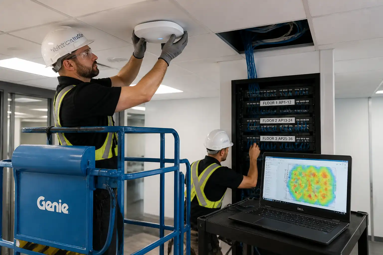

Method Statement: High‑Density Wi‑Fi Access Point Deployment, Commissioning, and RF Optimization – Method Statement
AI-assisted method statement with matching ITP, PDF download, and Excel export.
More than a static template
Unlike a downloadable Word or PDF template, this method statement is an AI-assisted editable starting point connected directly to a matching Inspection and Test Plan. Every section is structured, project-adaptable, and ready to export.
- AI-assisted drafting — Customize every section with AI for your specific project scope.
- Linked ITP — A matching inspection and test plan is generated alongside the method statement.
- Multiple export formats — Download as a formatted PDF or editable Excel spreadsheet.
- Editable starting point, not a final document — Review, verify, and adjust all content against your project requirements before use.
Static template vs. Quollnet workflow
| Feature | Static template | Quollnet |
|---|---|---|
| Project-specific content | Manual fill-in required | AI-assisted customization |
| Linked ITP | Separate document, no link | Matching ITP included |
| Export formats | Usually PDF only | PDF and Excel |
| Structured sections | Free-form layout | 13 standardized sections |
| Saved to your account | Local file only | Cloud-saved, reusable |
| Content accuracy | You verify everything | AI-assisted, you still verify |
| Cost | Often free but time-intensive | Free to customize and download |
What you can customize
When you save this method statement to your account, every section becomes editable. The following 13 sections are included:
- Scope — Defines the activity and its boundaries.
- References — Standards, specifications, and drawings.
- Responsibilities — Roles and accountabilities.
- Resources — Labour, plant, and equipment summary.
- Materials — Materials and compliance requirements.
- Equipment — Tools and equipment details.
- Prerequisites — Hold points and pre-conditions.
- Method sequence — Step-by-step construction sequence.
- Safety controls — HSE risk controls and PPE.
- Environmental controls — Environmental mitigation measures.
- QA/QC — Quality inspection and test requirements.
- ITP — Inspection and Test Plan table (has its own page).
- Attachments — Referenced drawings and documentation.
Why this method statement is used
This method statement is used to define and communicate the approved procedure for carrying out method statement: high‑density wi‑fi access point deployment, commissioning, and rf optimization on site. It ensures the work is planned in advance, the correct resources and controls are in place, and all personnel understand responsibilities, sequence, quality requirements, and safety controls before work begins. It aligns site execution with the documented scope and acceptance expectations.
Who uses this method statement
This method statement is used by contractors, site supervisors, project engineers, QA/QC engineers, HSE officers, consultants, and client representatives. It serves as a shared reference for planning, execution, supervision, inspection, and approval of the activity on site.
When it is prepared and submitted
The method statement is prepared before the work activity starts and submitted as part of the pre-construction documentation package for review and approval.
Who reviews or approves it
The method statement is usually submitted to the client representative, consultant, resident engineer, or project management consultant for review and approval before the work commences.
Important approval note
This method statement is an AI-assisted editable starting point, not a pre-approved document. Before use on any project, all content must be reviewed and approved by the relevant parties (superintendent, principal contractor, or client representative) in accordance with your contract and project quality plan.
For example: if your specification requires a departure from a referenced standard, that departure must be documented and approved separately — this method statement will not capture that automatically. Always verify against your applicable drawings, specifications, and regulatory requirements.
Method statement content
Scope
Overview
This method statement covers engineering, installation, testing, and optimization of a high‑density enterprise Wi‑Fi network, including:
- Ceiling grid mounting of indoor access points (APs) with structural reinforcement and safety tethers.
- Installation and certification of Cat6A permanent links to each AP location, including labeling and records.
- Enterprise switch configuration (VLANs, QoS, mGig/PoE, security) and controller/WLAN configuration (RF profiles, roaming optimizations).
- Post‑installation active RF heat mapping, signal‑to‑noise ratio (SNR) verification, and client roaming performance testing.
- Documentation, QA/QC verification, ITP execution, and handover.
Locations
- Office floors, meeting rooms, corridors, atria, and special spaces as indicated on approved drawings. Ceiling types include suspended T‑bar grid and exposed soffit.
Exclusions
- Structural modifications beyond approved ceiling reinforcement methods.
- Core drilling through structural members unless separately approved.
- Remediation of legacy cabling not identified in design.
Deliverables
- Certified test results (Cat6A permanent link), RF heat maps, SNR/coverage compliance report, roaming test logs, as‑built drawings, switch/WLC configuration backups, labeling schedule, O&M manuals, and redlines.
[Verify per project specifications]
References
| Document Type | Reference / Number | Revision | Notes |
|---|---|---|---|
| Standard | ISO/IEC 11801-1 | Benchmark for Cat6A permanent link limits [Verify per project specifications]. | |
| Standard | ANSI/TIA-568.2-D; ANSI/TIA-1152-A | Field certification criteria for Cat6A PL/CH. | |
| Standard | ANSI/TIA-569-D; ANSI/TIA-606-C; ANSI/TIA-607-C | ||
| Standard | IEEE 802.3af/at/bt | Validate AP required PoE class per datasheet [Verify per AP model]. | |
| Standard | IEEE 802.11ax/6E; 802.11k/v/r/e | Optimize for high-density; enable assisted roaming where supported. | |
| Guideline | BICSI 005; BICSI 008 | Use as good practice where project lacks explicit detail. | |
| Code | NFPA 70 (NEC) / IEC 60364 | Apply per jurisdiction [Verify per local code]. | |
| Standard/Regulation | UL, CE, FCC OET 65, ICNIRP | Keep EIRP within regulatory limits [Verify per country]. | |
| Standard | UL System Listings; NFPA 90A; EN 1366-3 | Use manufacturer’s listed systems only. |
Responsibilities
| Role | Responsibility | Name / Party |
|---|---|---|
| PM | Approve method/ITP; escalate risks; client interface. | Contractor |
| HSE | Enforce controls for WAH, ceiling access, electrical rooms. | Contractor |
| QA/QC | Verify certifications, labeling, documentation. | Contractor |
| Engineer | Peer review configs; implement MOPs within change window. | Contractor |
| Engineer | Issue final RF compliance report and heat maps. | Contractor |
| Supervisor | Daily checks; quality gate before AP install. | Contractor |
| Technicians | Follow drawings and method; maintain housekeeping. | Contractor |
| Client | Witness tests; accept go‑live. | Client |
Resources
| Resource Type | Description | Quantity | Remarks |
|---|---|---|---|
| Human | CCNP/Equivalent; switch/WLC config. | 1-2 | |
| Human | Ekahau/CWNP certified; surveys and optimization. | 1 | |
| Human | Supervisor + technicians for installation and testing. | 3-7 | |
| Human | Licensed for scissor/boom lift. | 1 |
Materials
| Material | Specification / Grade | Quantity | Remarks |
|---|---|---|---|
| AP | UL/CE listed; country approved | Per drawings | |
| Brackets/Hardware | Per AP vendor | Per AP | |
| Cable | ANSI/TIA‑568.2‑D; ISO/IEC 11801-1 | Per AP | |
| Connectivity HW | Cat6A; PoE rated | As required | |
| Firestop | UL listing; EN 1366‑3 | As required | |
| Labeling | TIA‑606‑C | As required | |
| Patch Cords | Cat6A; PoE rated | As required |
Equipment
| Equipment | Capacity / Type | Quantity | Inspection Required |
|---|---|---|---|
| DSX-XXXX | 1+ | Yes | |
| Sidekick 2 | 1 | Yes | |
| PoE analyzer | 1-2 | Yes | |
| MEWP | As needed | Yes | |
| Assorted | Set | Yes | |
| Brady/Brother | 1 | ||
| Windows/macOS | 2-3 |
Prerequisites
Approvals and Permits
- Approved for Construction (AFC) drawings with AP locations and IDs.
- Method Statement and ITP approved by Client/Consultant.
- Permits to Work: working at height, above-ceiling access, electrical room access, hot works (if drilling anchors), IT change window MOP. [Verify per project HSE plan and local regulations]
Site Readiness
- Ceiling grid integrity verified; damaged tiles replaced.
- Pathways clear; J‑hooks/trays available; penetrations identified.
- IDF/MDF racks powered, grounded, and reachable; switch ports reserved.
- RF design/predictive model available and reviewed.
Materials & Tools
- OEM AP brackets/backing plates and safety tethers on site.
- Calibrated certifier and RF survey kit available with valid licenses.
- Firestop systems and documentation available.
Notifications
- Stakeholders notified of potential disruptions; out‑of‑hours work scheduled as required.
Training
- Toolbox talk for task‑specific hazards and emergency procedures; MEWP operators licensed; technicians briefed on ceiling grid load limitations.
Method Sequence
| Step | Activity | Description | Responsibility | Inspection / Hold Point |
|---|---|---|---|---|
| 1 | Pre‑Start Coordination | Review AFC drawings, RF design, and MOP. Conduct area walkdown; mark AP positions on grid using laser and plumb. Verify clearances ≥1.0 m from diffusers/return grilles where practicable [Verify]. | PM / RF Engineer / Cabling Sup. | ITP Hold Point: layout verification |
| 2 | Ceiling Grid Preparation | Install OEM T‑bar bracket and backing plate. Add independent safety tether to structure (ceiling slab/beam) using approved anchor/clip. Do not impose dead load on tile alone. Reinforce per seismic requirements where applicable. | Cabling Techs / Sup. | Visual check; torque check |
| 3 | Cable Pulling (Horizontal) | Route Cat6A from IDF/MDF to AP via trays/J‑hooks. Maintain support spacing ≤1.2 m; bend radius ≥4×OD (U/UTP) or ≥8×OD (F/UTP) [Verify]; max pull tension ≤110 N or per manufacturer; separation from power per TIA‑569‑D (typical 50–300 mm depending on power). Provide 1 m service loop at AP and at rack where space permits. | Cabling Crew | In‑progress inspection |
| 4 | Penetrations & Firestopping | Install sleeves/bushings where crossing fire barriers. After cable installation, apply UL‑listed firestop system as per tested assembly; affix label at penetration. | Cabling Crew | Witness point before close-up |
| 5 | Termination (AP Outlet/Consolidation Point) | Terminate to Cat6A jack/module per T568B. Maintain pair twist to within 13 mm of termination. Use shield bonding for F/UTP as per TIA‑607‑C. | Cabling Techs | Spot check by Supervisor |
| 6 | Patch Panel Termination | Dress and terminate at rack. Label per TIA‑606‑C (cabinet-row-U-location/port). Earth bonding per TIA‑607‑C. | Cabling Techs | Supervisor check |
| 7 | Cable Certification | Test 100% permanent links with Level VI/2G field tester to Cat6A limits (up to 500 MHz): length, wiremap, NEXT/PSNEXT, ACR‑F, Return Loss, Prop Delay, Delay Skew. | QA/QC / Cabling Sup. | ITP Hold Point: review results |
| 8 | Labeling & Records | Apply AP ID at grid and on cable ends. Update as‑built with AP IDs, cable IDs, patch panel ports. | Cabling Crew / QA | Random audit 10% |
| 9 | AP Hardware Installation | Mount AP to OEM bracket; connect patch cord; secure slack; verify MAC/serial; ensure LED visible. Maintain clearance; avoid metal obstructions; confirm tether intact. | Cabling Techs | 100% visual |
| 10 | Switchport Provisioning | Configure switchport as trunk or AP access uplink per vendor: allowed VLANs, native/tagged management VLAN, PoE enable, mGig (2.5/5G) if supported, STP guard, LLDP. Validate power budget. | Network Engineer | Peer review |
| 11 | WLAN Controller/RF Profile | Create SSIDs/VLAN mapping; enable WPA2/WPA3‑Enterprise [Verify]; 802.11k/v; 802.11r (FT) for supported clients; DCA/TPC with 5 GHz (20 MHz channels) for HD; 6 GHz per design; limit 2.4 GHz or low power; minimum data rate 12–24 Mbps [Verify]; client load‑balancing; band‑steering. | RF/Wi‑Fi Engineer | Peer review |
| 12 | PoE Validation & AP Join | Power up APs; verify LLDP negotiated power, draw under load, and join to controller. Check firmware version and auto‑upgrade if in MOP. | Network Engineer | Functional check |
| 13 | Post‑Install Active RF Survey | Perform walking survey (Ekahau/Sidekick) on all floors per grid: measurement point spacing 3–5 m. Capture RSSI, SNR, retries, CCI/ACI. Mark any coverage holes and interference sources. | RF Engineer | Witness point |
| 14 | RF Optimization | Adjust channel/power plans, minimum data rates, band utilization; re‑survey spot areas until KPIs met. | RF Engineer | Engineer sign‑off |
| 15 | Client Roaming Tests | Conduct walk tests with two device classes (smartphone and VoIP handset/laptop) along defined routes. Log roam times, packet loss, jitter, MOS (if voice), throughput. | RF/Network Engineer | Witness point |
| 16 | Security & QoS Validation | Validate 802.1X/EAP‑TLS authentication; correct VLAN assignment; WMM access categories; DSCP mapping from WLAN to wired QoS. | Network Engineer | Peer review |
| 17 | Monitoring & Backups | Add switches/APs/WLC to NMS/Syslog/SNMP; set thresholds; take final backups; document power budgets and port mappings. | Network Engineer | Config audit |
| 18 | Handover & Training | Deliver documentation set; conduct client walkthrough of RF results, port/VLAN maps, and operational procedures. | PM / Engineers | Final review |
Health, Safety, and Environment (HSE) – Task-Specific Safety Controls
Key Hazards, Consequences, and Controls
1) Working at Height (ladders/MEWP)
- Consequence: Fall from height causing serious injury/fatality.
- Engineering/Procedural Controls: Use MEWP for heights >2 m where feasible; select correct ladder; maintain 3 points of contact; exclusion zone; MEWP pre‑use inspection; do not overreach; fit guardrails.
- PPE: Harness and lanyard in MEWP; hard hat with chin strap; safety footwear; gloves.
- Collective Measures: Barriers and signage; spotter during MEWP operations.
- Inspection/Permit/Supervision: PTW for WAH; daily MEWP inspection log; competent operator; supervisor oversight. [Verify per project HSE plan and local regulations]
2) Ceiling Grid/Tile Failure
- Consequence: AP falls; injuries; ceiling damage.
- Controls: Use OEM T‑bar brackets and separate safety tether to structure; never hang from tile only; verify grid condition before work; replace damaged tiles; adhere to seismic requirements where applicable.
- PPE: Hard hat, gloves, eye protection.
- Collective Measures: Work platform; controlled area beneath task.
- Inspection/Permit/Supervision: Supervisor verification; torque checks; photographic record.
3) Above‑Ceiling Dust and Debris
- Consequence: Eye/respiratory irritation; contamination of occupied areas.
- Controls: Use dust extraction on drills; damp wipe; cover sensitive equipment; HEPA vac; work after hours where needed.
- PPE: Safety glasses; FFP2/N95 mask; gloves.
- Collective Measures: Temporary containment/curtains if required.
- Inspection/Permit/Supervision: Housekeeping inspections; client FM coordination.
4) Electrical Rooms and PoE Exposure
- Consequence: Electrical shock, arc‑flash (from electrical distribution); minor shock/burn from LV circuits unlikely but possible.
- Controls: Access only to telecom racks; observe electrical clearances; no live work on mains; isolate where required; follow LOTO for any mains work (if applicable). PoE testing with insulated tools.
- PPE: Electrical‑rated gloves when required; safety footwear; eye protection.
- Collective Measures: Barriers; restricted access.
- Inspection/Permit/Supervision: Electrical room PTW; trained personnel; supervisor sign‑in.
5) Manual Handling and Repetitive Tasks
- Consequence: Musculoskeletal injuries.
- Controls: Team lifts for ladders/MEWP components; use trolleys; rotate tasks; keep loads <20–25 kg per person [Verify].
- PPE: Gloves; safety footwear.
- Collective Measures: Mechanical aids.
- Inspection/Permit/Supervision: Manual handling training; supervision.
6) Penetrations and Fire Integrity
- Consequence: Loss of fire compartmentation and smoke spread.
- Controls: Identify barriers; use listed firestop systems only; label and document; QA inspection before close‑up.
- PPE: Gloves; eye protection.
- Collective Measures: Hot works permit if drilling; spark control.
- Inspection/Permit/Supervision: Firestop inspection; permit where drilling anchors.
7) Occupied Premises and Public Interface
- Consequence: Trips, struck‑by from overhead work, noise complaints.
- Controls: Barricade work area; spotter; schedule noisy tasks out of hours; tidy cabling; cable mats.
- PPE: Hi‑vis; safety footwear.
- Collective Measures: Floor wardens; signage.
- Inspection/Permit/Supervision: Daily safety walks; client liaison.
8) Ladder/Tool Drops
- Consequence: Injury to persons below; equipment damage.
- Controls: Tool lanyards; exclusion zone; do not store items on top of ladders; keep both hands free when climbing.
- PPE: Hard hat; safety footwear.
- Collective Measures: Spotter; barricades.
- Inspection/Permit/Supervision: Supervisor checks; TBT emphasis.
9) Asbestos or Hazardous Materials (legacy buildings)
- Consequence: Exposure to asbestos/lead/silica.
- Controls: Review asbestos register; no disturbance without survey and clearance; stop work if suspicious materials found.
- PPE: As directed by survey (e.g., P3), disposable coveralls when required.
- Collective Measures: Area isolation; licensed removal if needed.
- Inspection/Permit/Supervision: Permit and clearance certificates before intrusive works.
Emergency Preparedness: First aid kit and trained first aider available; emergency contacts posted; MEWP rescue plan; spill kit for batteries/chemicals if applicable.
Environmental Controls
- Waste Management: Segregate packaging, scrap cable (recycle copper), and e‑waste (legacy APs) through licensed handlers; maintain waste transfer notes.
- Noise and Working Hours: Plan drilling and testing during agreed windows; use low‑noise tools; notify occupants.
- Dust Control: HEPA vacs; damp wiping; temporary containment near sensitive areas.
- Fire Integrity: Restore firestopping to original rating using listed systems; record locations and materials used.
- Energy & Thermal: Validate PoE classes to avoid over‑provision; enable RF features that reduce airtime contention and energy (e.g., optimized power); consider scheduled radios where permitted. [Verify per client policy]
- Chemical/VOC: Use low‑VOC adhesives/sealants where possible; follow SDS.
- Transport & Storage: Store APs and electronics in dry, temperature‑controlled rooms (typically 0–40°C) per manufacturer datasheets; avoid condensation.
Quality Assurance and Quality Control (QA/QC)
General
- Apply ITP with defined hold/witness points for layout verification, cable certification review, firestopping, RF survey, and roaming tests.
Cabling Quality
- 100% permanent link certification (Cat6A). Any FAIL results investigated; re‑termination or cable replacement as needed; retest until PASS.
- Visual standards: neat dressing, correct bend radius, proper support spacing, labeled per TIA‑606‑C.
Hardware Installation
- OEM mounting kits only; safety tether to structure; aesthetic alignment; torque per vendor where specified [Verify].
Network Configuration
- Peer review of switch and WLC configurations before implementation. Maintain MOP and change ticket; capture pre/post "show" outputs. Validate PoE budgets per switch/stack.
RF and Roaming Performance
- Active survey with measurement spacing 3–5 m, post‑optimization meeting: RSSI ≥‑67 dBm (target SSID) over ≥95% of usable area, SNR ≥25 dB (voice zones ≥30 dB), and co‑channel occupancy ≤3 APs at >‑85 dBm. Roaming handoff <150 ms for voice; packet loss during roam <1%; jitter <30 ms.
Documentation & Handover
- Submit: DSX test reports, RF survey project files (e.g., .esx) and heat map PDFs, AP inventory (MAC/serial/location), switch/WLC backups, PoE budget sheet, as‑built drawings (PDF/CAD), labeling schedule, firestop log, permits, and training attendance.
Nonconformance
- Record NCRs for any deviations; apply corrective actions; re‑inspect. Maintain RFI log for design queries.
Attachments
- AFC drawings with AP IDs and locations
- Sample mounting detail and OEM instructions
- TIA‑606‑C labeling scheme and examples
- MOPs for switch/WLC changes with back‑out plans
- Risk Assessment/Method Statement (RAMS) and PTW templates
- Daily pre‑use MEWP and ladder checklists
- Firestop system data sheets and UL listings
- Example DSX certification report template
- RF survey acceptance checklist and test routes
- Roaming test procedure with acceptance thresholds
- Training attendance sheet and toolbox talk records
This content is a read-only public reference. Download or customize to get an editable version.
ITP preview
The first inspection activities from the linked ITP for Method Statement: High‑Density Wi‑Fi Access Point Deployment, Commissioning, and RF Optimization:
| Activity | Inspection / Test | Acceptance Criteria | Responsibility | Record |
|---|---|---|---|---|
| Pre‑start layout verification | Check AP marks vs AFC | AP marks within ±150 mm or approved variance | PM / RF Engineer / QA | Hold point form; marked layout photos |
| Ceiling grid readiness | Visual condition; load path | Grid intact; no cracked tiles; structural tether point available | QA/QC / Supervisor | Checklist; photos |
| Mounting hardware installation | Torque/visual check | OEM bracket used; safety tether installed; no tile load | Supervisor / QA/QC | IR; photos |
Showing 3 of 16 inspection activities. View full ITP →
Related Inspection and Test Plan
An Inspection and Test Plan (ITP) is available for Method Statement: High‑Density Wi‑Fi Access Point Deployment, Commissioning, and RF Optimization. The ITP defines the inspection activities, acceptance criteria, hold and witness points, responsible parties, and records required to verify the work described in this method statement.
View the Method Statement: High‑Density Wi‑Fi Access Point Deployment, Commissioning, and RF Optimization ITP →