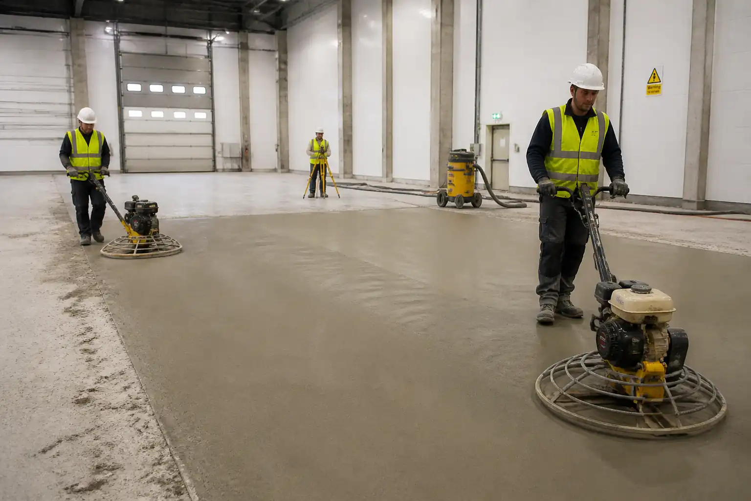

Inspection and Test Plan for Method Statement: Granolithic Screed Installation for Heavy Traffic Areas (Bonded System)
AI-assisted inspection and test plan connected to a method statement, with PDF and Excel export.
More than a static template
Unlike a downloadable Word or PDF template, this ITP is an AI-assisted editable starting point directly connected to its method statement. Every inspection activity, hold point, and acceptance criterion is structured and ready to adapt to your project.
- AI-assisted customization — Tailor inspection activities and acceptance criteria to your specific project scope.
- Linked method statement — This ITP is connected to the corresponding method statement describing the work sequence.
- Multiple export formats — Download as a formatted PDF or editable Excel spreadsheet.
- Editable starting point, not a final document — Review and verify all content against your project specifications and standards before use.
What you can customize
When you save this ITP to your account, every inspection row becomes editable. You can add, remove, or modify:
- Inspection activity — Description of what is being inspected.
- Inspection type — Hold point (H), Witness point (W), Review (R), or Monitor (M).
- Responsibility — Contractor, subcontractor, engineer, or client.
- Frequency — How often the inspection occurs.
- Acceptance criteria — Referenced standard or specification requirement.
- Records — Forms, test reports, or checklists required as evidence.
Why this ITP is used
To control quality and compliance of heavy-duty screed installation via defined inspections, tests, and acceptance criteria.
Who uses this inspection and test plan
QA/QC engineers, site supervisors, and the Engineer/Client Representative for surveillance and approvals.
When this ITP is prepared and submitted
From pre-start material approvals through substrate acceptance, during placement, and at post-cure testing before handover.
Who receives or approves this ITP
Engineer/Client Representative for review and approval before works commence.
Inspection scope
Material conformance, substrate competency, bond preparation, placement controls, finishing and curing, flatness/regularity, and ISCR hardness.
Typical hold, witness, and review points
H1 – Substrate prep & acceptance; H2 – Trial bay approval; W1 – Bond coat & start of pour; W2 – Flatness checks; H3 – ISCR testing & final acceptance.
Typical inspection records
Material approvals, batch records, bond coat logs, thickness/flatness sheets, ISCR certificates, curing logs, as-built drawings, NCR/CAR closeout.
Important approval note
This ITP is an AI-assisted editable starting point, not a pre-approved document. Before use on any project, all inspection activities, hold points, and acceptance criteria must be reviewed and approved by the relevant parties (superintendent, principal contractor, or client representative) in accordance with your contract and project quality plan.
Always verify acceptance criteria against your applicable drawings, specifications, and regulatory requirements. Hold points must be confirmed with the relevant authority before work proceeds past that point.
Inspection and test plan
| Activity | Inspection / Test | Acceptance Criteria | Responsibility | Record |
|---|---|---|---|---|
| Materials delivery and approvals | Review COCs, SDS, admixture TDS, batch tickets | Conformance to EN/ASTM standards; approvals on file | QA/QC Engineer / Engineer Rep | Material approval, delivery tickets |
| Substrate pull-off testing (prior to screeding) | Tensile pull-off tests (random grid) | ≥1.5 MPa typical for bonded screed [Verify per spec] | QA/QC Engineer | Pull-off test report, map |
| Surface preparation inspection (Hold Point H1) | Visual/cleanliness; CSP profile; repairs complete | CSP 5–7; dust-free; defects repaired; SSD achievable | QA/QC Engineer / Engineer Rep | H1 release form, photos |
| Mock-up/trial bay (Hold Point H2) | SR checks; finish quality; preliminary ISCR (as time allows) | Meets specified SR and finish; indicative ISCR acceptable | QA/QC Engineer / Engineer Rep | H2 approval, trial bay report |
| Bond coat application (Witness W1) | Coverage and timing vs open time | Full coverage; screed placed within window | Site Supervisor / QA/QC | Bond coat log |
| Screed placement and compaction | Batch consistency; compaction method; edgework | Uniform semi-dry mix; dense compacted surface | Site Supervisor / QA/QC | Daily pour log |
| Thickness verification | Spot checks at pins/cores (if required) | Within ±5 mm; ≥min thickness at all points | QA/QC Engineer | Thickness check sheet |
| Surface regularity/flatness (Witness W2) | 2 m straightedge grid or F-number survey | BS SR2 or SR1; or FF/FL per spec [Verify] | QA/QC Engineer | Flatness report |
| Curing application | WFT/coverage verification; protection in place | Uniform curing; no missed areas; duration per spec | Site Supervisor / QA/QC | Curing log |
| ISCR testing (Hold Point H3) | BRE drop hammer tests per BS 8204-1 | Category A: avg ≤2.0 mm; single ≤3.0 mm [Verify] | QA/QC Engineer / Engineer Rep | ISCR test certificates |
| Final inspection and documentation | Walkthrough; docs review | All ITP items closed; NCRs resolved | Project Manager / QA/QC / Engineer Rep | Completion dossier, acceptance certificate |
This table is a read-only public reference. Download the PDF or Excel version, or customize this ITP to edit it for your project.
Frequently asked questions
Related method statement
This Inspection and Test Plan is associated with the Method Statement: Granolithic Screed Installation for Heavy Traffic Areas (Bonded System) method statement, which describes the step-by-step construction sequence, resources, materials, equipment, safety controls, and environmental controls for this activity.
View the Method Statement: Granolithic Screed Installation for Heavy Traffic Areas (Bonded System) method statement →