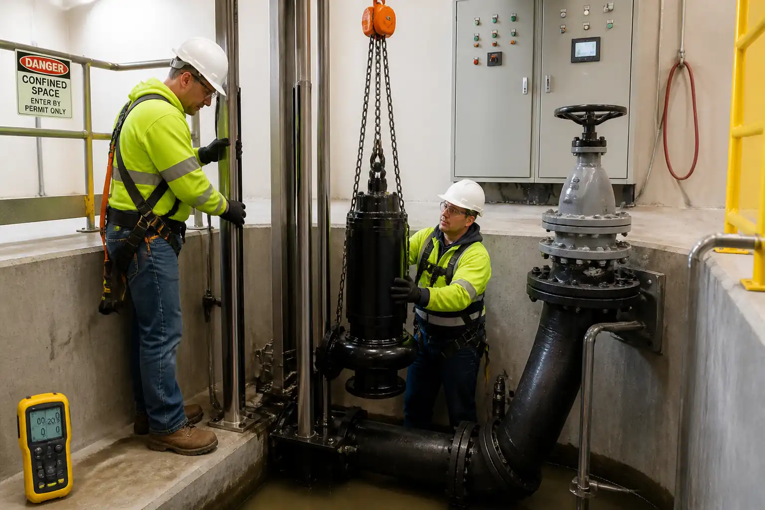

Method Statement: Installation and Mechanical Commissioning of Submersible Sewage Pumps – Method Statement
AI-assisted method statement with matching ITP, PDF download, and Excel export.
More than a static template
Unlike a downloadable Word or PDF template, this method statement is an AI-assisted editable starting point connected directly to a matching Inspection and Test Plan. Every section is structured, project-adaptable, and ready to export.
- AI-assisted drafting — Customize every section with AI for your specific project scope.
- Linked ITP — A matching inspection and test plan is generated alongside the method statement.
- Multiple export formats — Download as a formatted PDF or editable Excel spreadsheet.
- Editable starting point, not a final document — Review, verify, and adjust all content against your project requirements before use.
Static template vs. Quollnet workflow
| Feature | Static template | Quollnet |
|---|---|---|
| Project-specific content | Manual fill-in required | AI-assisted customization |
| Linked ITP | Separate document, no link | Matching ITP included |
| Export formats | Usually PDF only | PDF and Excel |
| Structured sections | Free-form layout | 13 standardized sections |
| Saved to your account | Local file only | Cloud-saved, reusable |
| Content accuracy | You verify everything | AI-assisted, you still verify |
| Cost | Often free but time-intensive | Free to customize and download |
What you can customize
When you save this method statement to your account, every section becomes editable. The following 13 sections are included:
- Scope — Defines the activity and its boundaries.
- References — Standards, specifications, and drawings.
- Responsibilities — Roles and accountabilities.
- Resources — Labour, plant, and equipment summary.
- Materials — Materials and compliance requirements.
- Equipment — Tools and equipment details.
- Prerequisites — Hold points and pre-conditions.
- Method sequence — Step-by-step construction sequence.
- Safety controls — HSE risk controls and PPE.
- Environmental controls — Environmental mitigation measures.
- QA/QC — Quality inspection and test requirements.
- ITP — Inspection and Test Plan table (has its own page).
- Attachments — Referenced drawings and documentation.
Why this method statement is used
This method statement is used to define and communicate the approved procedure for carrying out method statement: installation and mechanical commissioning of submersible sewage pumps on site. It ensures the work is planned in advance, the correct resources and controls are in place, and all personnel understand responsibilities, sequence, quality requirements, and safety controls before work begins. It aligns site execution with the documented scope and acceptance expectations.
Who uses this method statement
This method statement is used by contractors, site supervisors, project engineers, QA/QC engineers, HSE officers, consultants, and client representatives. It serves as a shared reference for planning, execution, supervision, inspection, and approval of the activity on site.
When it is prepared and submitted
The method statement is prepared before the work activity starts and submitted as part of the pre-construction documentation package for review and approval.
Who reviews or approves it
The method statement is usually submitted to the client representative, consultant, resident engineer, or project management consultant for review and approval before the work commences.
Important approval note
This method statement is an AI-assisted editable starting point, not a pre-approved document. Before use on any project, all content must be reviewed and approved by the relevant parties (superintendent, principal contractor, or client representative) in accordance with your contract and project quality plan.
For example: if your specification requires a departure from a referenced standard, that departure must be documented and approved separately — this method statement will not capture that automatically. Always verify against your applicable drawings, specifications, and regulatory requirements.
Method statement content
Scope
Scope of Works
- Install submersible wastewater pumps complete with guide rail system, auto-coupling (duckfoot) base, lifting chains, discharge piping/valves, and electrical/control integration in an existing/new wet well.
- Align and commission guide rails and auto-coupling to achieve repeatable, leak-tight seating.
- Connect discharge pipework to manifold/rising main, including isolation and non-return valves, supports, and flexible joints as specified.
- Install and set liquid level controls (float switches and/or level transmitter), configure control panel logic, and implement dry-run prevention.
- Perform pre-energization checks, hydrostatic testing of discharge pipework (where applicable), wet functional tests, and pump performance logging against approved curves.
- Deliver as-built documentation, calibration records, ITRs/WIRs, O&M and training. [Verify per project specifications]
References
| Document Type | Reference / Number | Revision | Notes |
|---|---|---|---|
| Standard | ISO 9906 | ||
| Standard | IEC 60034 (Parts 1, 11) / IEEE 43 (IR guidance) [Verify project requirement] | ||
| Standard | IEC 60364 series [or BS 7671 where applicable] | [Verify local code] | |
| Standard | BS EN 1092-1 (PN) or ASME B16.5 (Class) [Project standard governs] | ||
| Standard | EN 805 (water supply) – test method basis for rising mains [Adapt for wastewater service] | [Verify test pressure and duration per spec] | |
| Standard | BS 7121-1; EN 13155; EN 1492 series [Verify local regulations] | ||
| Standard | ISO 10816/20816 (applicable parts) [Field guidance] | Measurement approach for submerged units to be agreed | |
| Standard | ATEX/IECEx [Verify hazardous area classification] |
Responsibilities
| Role | Responsibility | Name / Party |
|---|---|---|
| PM | Project Manager | Contractor |
| Construction | Construction Manager / Site Engineer | Contractor |
| QC | Mechanical QC Inspector | Contractor |
| QC | Electrical QC Inspector | Contractor |
| Cx | Commissioning Engineer | Contractor |
| HSE | HSE Officer | Contractor |
| Engineer | Engineer/Employer’s Representative | Engineer |
Resources
| Resource Type | Description | Quantity | Remarks |
|---|---|---|---|
| Manpower | Mechanical supervisor + fitters | 4 | |
| Manpower | Electrical supervisor + electricians | 3 | |
| Manpower | Commissioning engineer + technician | 2 | |
| Manpower | Appointed person, rigger/slinger | 2-3 | |
| Manpower | Standby rescue team with tripod/winch | 2 |
Materials
| Material | Specification / Grade | Quantity | Remarks |
|---|---|---|---|
| Pump | IP68 motor, 400/690V or as specified, duty per schedule | As per BOQ | |
| Auto-coupling | Manufacturer matched set | Per pump | |
| Guide rails | Diameter per OEM, straightness ≤1 mm/m | Per well | |
| Pipe | PN10/PN16 typical [Verify] | As per drawings | |
| Valves | BS EN 1074 / AWWA [Verify] | Per line | |
| Jointing | |||
| Controls | As required | ||
| Electrical | IEC 60364 compliant | ||
| Fixings |
Equipment
| Equipment | Capacity / Type | Quantity | Inspection Required |
|---|---|---|---|
| Crane | 5–25 t typical [Verify] | 1 | LOLER/Third-party cert valid |
| Rigging | 1–3 t | 2–4 | Pre-use check |
| Torque wrench | 20–300 Nm (range) | 2 | Calibration |
| IR tester | Up to 1000 V | 1 | Calibration |
| Electrical test | 1 each | Calibration | |
| Gas detector | 2 | Calibration | |
| Rescue | 150 kg+ | 1 | Pre-use |
| Ventilation | >500 m3/h typical | 1–2 | Pre-use |
| Hydrotest set | Up to test pressure | 1 | Calibration |
| Flowmeter | 1 | Calibration |
Prerequisites
Pre-Start Requirements
- Approved shop drawings, pump datasheets, GA drawings, wiring diagrams, and control logic narrative.
- Approved Method Statement and ITP; task risk assessment (TRA/JSA) briefed to all personnel.
- Permits: Lifting, Confined Space Entry, Electrical LOTO, Hot Work (if any), Excavation (if external works), as applicable. [Verify per project HSE plan and local regulations]
- Wet well structurally complete, cleaned, and free from debris; inflow isolated or bypassed; temporary plugs/blinds installed as required.
- Benchmarks and reference levels established; start/stop/high alarm elevations confirmed with Engineer.
- OEM installation manuals for pumps and guide rails available at site; FAT reports (if applicable) reviewed.
- All instruments calibrated; torque charts available; anchors and grout with valid TDS; materials inspected and accepted.
- Hazardous area classification confirmed (if applicable) and equipment compliance verified.
- Power supply available and tested for voltage and fault level; control panel energized for testing after LOTO clearance.
Method Sequence
| Step | Activity | Description | Responsibility | Inspection / Hold Point |
|---|---|---|---|---|
| 1 | Site handover and permits | Conduct pre-start meeting; issue permits (Lifting, Confined Space, LOTO). Toolbox talk and TRA briefing. | Site Engineer / HSE | Permit verification |
| 2 | Delivery inspection | Verify pumps, rails, auto-couplings, valves, and materials against approved submittals. | QC / Storekeeper | Visual and dimensional |
| 3 | Wet well preparation | Isolate flows; clean well; gas test; ventilate; install temporary barriers/edge protection. | Site Engineer / HSE | Gas test & atmosphere control |
| 4 | Set out base and fixings | Mark base elbow and bracket positions; drill and install chemical anchors; grout as required. | Mechanical Supervisor | Pull-out capacity (if required) |
| 5 | Install auto-coupling base | Position duckfoot on base; align to riser; tighten flange bolts to specified torque. | Mechanical Supervisor | Flange joint inspection |
| 6 | Install guide rails and brackets | Fit upper guide bracket; plumb rails using spirit level/laser; secure with intermediate supports as needed. | Mechanical Supervisor | Dimensional survey |
| 7 | Trial lowering (dry) | Rig pump with certified slings to lifting eye; slowly lower without seating to check unobstructed travel and cable routing. | Rigger / Mechanical Supervisor | Rigging inspection |
| 8 | Final seating | Lower pump to engage auto-coupling; confirm full contact of mating faces; raise 200–300 mm and re-seat to confirm repeatability. | Mechanical Supervisor / QC | Seating verification |
| 9 | Discharge piping and valves | Install riser/valves/supports. Apply gasket, align flanges, tighten in star pattern to specified torque. | Mechanical Supervisor | Piping inspection |
| 10 | Electrical cabling and terminations | Route pump power/control cables; fit IP68 glands; terminate in JB/panel; identify cores; earth bonding. | Electrical Supervisor | Electrical inspection |
| 11 | Protection and settings | Set overloads at 1.05× FLA (cold) unless OEM states otherwise; configure seal/thermal relays; VFD parameters (if any). | Commissioning Engineer | Panel settings review |
| 12 | Pre-energization tests | IR test (stator to earth) at 500 VDC for LV motors; record polarization index if required; verify phase rotation at panel/JB; continuity and insulation on control circuits. | Electrical QC | Electrical tests |
| 13 | Hydrostatic test (if applicable) | Isolate pump; pressurize discharge line to 1.5× design pressure or PN rating (lower of the two); hold 30 min. | Mechanical Supervisor / QC | Pressure test |
| 14 | Float switch installation and setting | Install weights and set elevations: Stop (lowest), Start (duty), Assist (lead/lag), High-High Alarm. Secure to cable holders/ hooks. | Commissioning Engineer | Level setout check |
| 15 | Dry-run prevention test | With clean water, run pump then lower level to Stop; verify trip/interlock: stop at Stop level; seal/thermal alarms; VFD dry-run logic if present. | Commissioning Engineer / Electrical QC | Functional test |
| 16 | Wet functional test (duty/assist) | Fill well; verify Duty starts at Start; Assist starts at Assist setpoint; check non-return valve operation and discharge pressure. | Commissioning Engineer | Operational check |
| 17 | Performance logging | Stabilize at duty point; record flow, discharge pressure, voltage/current per phase, PF, frequency/VFD speed, and vibration (if measurable). | Commissioning Engineer / QA | Performance verification |
| 18 | Demobilization and handover | Remove temporary works; reinstate covers; submit as-builts, logs, ITRs, O&M; train operator. | Site Engineer / Commissioning Engineer | Document review |
Health, Safety and Environment (HSE) – Safety Controls
Task-Specific Hazards and Controls
- Hazard: Lifting over open wet well; pump drop
- Likely consequence: Serious injury/fatality, equipment damage
- Control: Appointed Person lift plan; exclusion zone; certified crane and slings; taglines; no personnel under load
- Required PPE: Helmet with chin strap, gloves, safety boots, eye protection
- Collective measure: Edge protection/guardrails around wet well; barricades and signage
-
Inspection/permit: BS 7121-compliant lift plan; pre-use inspection of lifting gear; Lifting Permit [Verify per project HSE plan and local regulations]
-
Hazard: Confined space entry (wet well)
- Likely consequence: Asphyxiation/toxic exposure (H2S/CH4), drowning, entrapment
- Control: Confined Space Permit; continuous gas monitoring (O2, H2S, CH4/LEL, CO); forced ventilation; standby rescue team with tripod/winch; harness and lifeline; communication plan; water level isolation/bypass
- Required PPE: Full body harness, multi-gas detector, chemical-resistant gloves, boots, hard hat, eye protection
- Collective measure: Rescue plan drilled; barriered access; intrinsically safe lighting where required
-
Inspection/permit: Permit with atmospheric readings; bump test records; rescue equipment inspection tags
-
Hazard: Electrical energization/LOTO failure
- Likely consequence: Electric shock, arc flash, equipment damage
- Control: LOTO procedure; verified de-energization before termination; use of RCDs; correct phase rotation verification; IP68 glands and strain relief
- Required PPE: Electrically rated gloves, arc-rated face shield/clothing (as required), safety boots
- Collective measure: Barriers around panels; insulated tools; lock boxes and tags
-
Inspection/permit: Electrical work permit; LOTO audit; instrument calibration certificates
-
Hazard: Exposure to sewage aerosols/biological agents
- Likely consequence: Illness, infection
- Control: Hygiene controls, vaccination status [Verify]; minimize agitation; use clean water for testing; decontaminate equipment after use
- Required PPE: Nitrile/chemical gloves, coveralls, eye/face protection, boots
- Collective measure: Handwash station; dedicated waste bags/containers
-
Inspection/permit: HSE inspection; COSHH assessment (if chemicals used)
-
Hazard: Pressurization during hydrotest
- Likely consequence: Line/component rupture, projectile hazards
- Control: Rated test equipment; calibrated gauges; test blinds; gradual pressurization; exclude personnel from line of fire
- Required PPE: Helmet, gloves, eye protection, boots
- Collective measure: Barriered test area; pressure relief
-
Inspection/permit: Hydrotest procedure approval; gauge calibration record
-
Hazard: Slips/trips at wet well area (wet surfaces, hoses, cables)
- Likely consequence: Sprains/fractures
- Control: Good housekeeping; cable management; anti-slip mats; adequate lighting (24 V where required)
- Required PPE: Safety boots with slip-resistant sole
- Collective measure: Route marking; tidy-up schedules
-
Inspection/permit: HSE walkdowns; lighting checks
-
Hazard: Noise and vibration from running pumps/blowers
- Likely consequence: Hearing damage
- Control: Limit exposure time; select low-noise equipment; maintain covers closed during operation
- Required PPE: Hearing protection where >85 dB(A)
- Collective measure: Noise mapping and signage
-
Inspection/permit: Noise monitoring records
-
Hazard: Hot works (if any bracket welding)
- Likely consequence: Burns, fire, fumes
- Control: Hot Work Permit; fire watch; fire blankets/extinguishers; gas-free verification in confined space
- Required PPE: Welding mask, gloves, FR clothing
- Collective measure: Spark containment; ventilation
- Inspection/permit: Hot Work Permit; gas readings [Verify]
Environmental Controls
Environmental Risk Controls
- Sewage and contaminated water management
- Control: Bypass/containment; use clean water for testing; collect and dispose of contaminated residues via licensed contractor.
-
Inspection/permit: Method for disposal approved by Engineer; waste transfer notes.
-
Dechlorination (if using chlorinated potable water for testing)
- Control: Neutralize before discharge using approved agent; verify residual chlorine < permissible limit.
-
Inspection/permit: Sampling per local standards [Verify].
-
Spill prevention
- Control: Drip trays under flanged joints; spill kits at point-of-work; immediate clean-up.
-
Inspection/permit: HSE inspections; spill log.
-
Noise and working hours
- Control: Comply with permitted hours; use silencers on blowers/pumps where feasible.
-
Inspection/permit: Community/noise compliance checks.
-
Waste segregation
- Control: Segregate scrap metal, packaging, used gaskets, and consumables; dispose per waste plan.
- Inspection/permit: Waste register; toolbox briefings.
QA/QC Requirements
Quality Assurance and Control
- Submittals: Approved datasheets, pump curves, GA drawings, I/O lists, software/logic description, torque tables, anchor TDS, calibration certificates.
- Calibration: All measuring equipment within validity; record serial numbers on ITRs.
- Inspection Requests (WIR/ITR): Submitted 24–48 hours prior for hold/witness points per ITP.
- Dimensional and Alignment Checks: Guide rail plumbness, spacing, and seating verification documented.
- Bolting Control: Use calibrated torque wrenches; record torque values and sequence.
- Electrical Tests: IR tests with ambient correction where required; rotation check; protection setting sheets signed.
- Hydrostatic Test: Procedure approval; calibrated gauges; acceptance documented.
- Functional/Performance Tests: Test sheets include water levels, setpoints, current/voltage, flow, head, alarms, and vibration (if measurable). Compare against ISO 9906 acceptance and nameplate FLA.
- Non-Conformance: NCR raised for deviations; corrective actions recorded and re-tested.
- Records/Handover: As-builts, redlines, O&M manuals, spares list, training records, ITRs, permits, calibration certificates, performance logs.
Attachments
Attachments / Appendices
- Approved pump datasheets and curves (duty/assist/standby) with ISO 9906 acceptance grade.
- OEM installation manuals for pumps, guide rails, and auto-couplings.
- Control philosophy and cause & effect for level devices and alarms.
- Torque tables for flanged joints and bracket fixings.
- Anchor manufacturer TDS and installation guide; grout TDS.
- Lift plan, rigging study, and certificates for lifting gear.
- Calibration certificates for torque wrenches, pressure gauges, flowmeters, and electrical testers.
- ITR/WIR templates: seating check sheet, torque log, level setting sheet, IR/rotation sheet, pressure test certificate, performance log.
- As-built drawings and redlines showing final elevations and cable routing.
This content is a read-only public reference. Download or customize to get an editable version.
ITP preview
The first inspection activities from the linked ITP for Method Statement: Installation and Mechanical Commissioning of Submersible Sewage Pumps:
| Activity | Inspection / Test | Acceptance Criteria | Responsibility | Record |
|---|---|---|---|---|
| Material receiving inspection | Check datasheets, nameplates, certificates | Conforms to approved submittals; no damage/corrosion | QC Inspector / Engineer (Witness) | Material Inspection Report (MIR) |
| Anchor installation | Embedment depth/spacing; TDS compliance | As per manufacturer; curing per TDS [Verify] | QC Inspector (Hold) | Anchor ITR/Photos |
| Auto-coupling base installation | Levelness; flange torque | Flatness within 1 mm; torque within specified range | QC Inspector / Engineer (Witness) | Torque Log; WIR |
Showing 3 of 14 inspection activities. View full ITP →
Related Inspection and Test Plan
An Inspection and Test Plan (ITP) is available for Method Statement: Installation and Mechanical Commissioning of Submersible Sewage Pumps. The ITP defines the inspection activities, acceptance criteria, hold and witness points, responsible parties, and records required to verify the work described in this method statement.
View the Method Statement: Installation and Mechanical Commissioning of Submersible Sewage Pumps ITP →