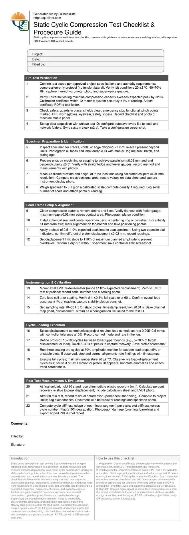
Static Cyclic Compression Test: Checklist and Procedures
Definition: Static cyclic compression test procedure for construction materials and components, guiding technicians through controlled axial load cycling, recovery measurements, and degradation evaluation while explicitly excluding tension and lateral actions.
- What: Apply axial compression cycles; measure recovery and stiffness degradation.
- Why: Quantify fatigue-like damage and residual strain under repeated loads.
- How: Displacement-controlled cycles, calibrated sensors, clear acceptance tolerances.
- Interactive, commentable, export, QR code: capture evidence and secure sign-offs.
Static cyclic compression test defines a controlled method to apply repeated axial compression to a specimen, capture recoveries, and evaluate stiffness degradation. Also called cyclic compressive loading or static cyclic loading, this protocol focuses on axial compression cycles only—tension and lateral actions are intentionally excluded. The checklist suits lab and site labs evaluating concrete, masonry units, elastomeric bearings, grout cubes, and similar materials. It reduces risks from misalignment, uncontrolled rates, drift, and data loss by prescribing calibrated equipment, displacement control, and evidence capture. Technicians gain consistent outcomes: recovery ratio, residual deformation, cycle-by-cycle stiffness, and qualitative damage. Supervisors get traceable documentation linked to project IDs, environmental conditions, and calibration certificates. Follow this step-by-step guide to set up the load frame, instrument the specimen, run pre-cycles, execute the full cyclic protocol, and complete post-test measurements and reporting. Use the interactive features to tick tasks, add comments and photos, and export PDF/Excel with a QR-secured audit trail.
- Use displacement-controlled cycles with calibrated sensors to quantify immediate recovery, residual deformation, and stiffness loss. Control rate within ±10%, keep temperature near 20 ±2 °C, and verify alignment under a small preload to minimize eccentric effects.
- Define a cycle protocol suited to the material: amplitude as a fraction of target compressive capacity or displacement, dwell times to capture creep/recovery, and a stable sampling rate. Pre-cycles seat the specimen and reveal setup issues before full loading.
- Interactive online checklist with tick, comment, and export features secured by QR code.
- Document all evidence for traceability: calibration certificates, environmental readings, configuration files, load–displacement plots, photographs of damage, and signed approvals. Archive raw data (.csv) and reports with consistent file names tied to the specimen ID and project.
Pre-Test Verification
Specimen Preparation & Identification
Load Frame Setup & Alignment
Instrumentation & Calibration
Cyclic Loading Execution
Post-Test Measurements & Evaluation
Control Strategy and Cycle Design
For static cyclic compression, displacement control is typically preferred because it maintains cycle amplitudes even as stiffness changes. Choose lower and upper bounds as fractions of the expected compressive capacity or as absolute displacements based on material behavior. Dwell periods at peaks (5–30 s) help quantify immediate recovery and short-term creep. Keep rates slow and stable (0.005–0.5 mm/s) to avoid dynamic effects; this is a static protocol, not high-frequency fatigue. Pre-cycles at reduced amplitude seat the specimen and expose setup issues before committing to full cycles. Maintain temperature near 20 ±2 °C, as stiffness and recovery are temperature dependent. Acceptance cues include rate within ±10% of setpoint, no sudden load drops >5%, and repeatable hysteresis loops after stabilization. Example: elastomeric bearing pads often use displacement bounds; concrete cylinders often use load-derived bounds converted to displacement once stiffness is known.
- Prefer displacement control for stability with changing stiffness.
- Set slow rates to avoid dynamic effects and heating.
- Use dwells to capture recovery and short-term creep.
- Run pre-cycles to seat and validate setup.
- Stabilize temperature near 20 ±2 °C for consistency.
Alignment, Seating, and Sensing
Misalignment biases results by introducing unintended bending, which inflates apparent degradation. Use a clean, flat platen pair and a spherical seat to accommodate minor angular mismatch. Center the specimen carefully; mark axes on both faces. Under a small preload (0.5–1.0% of peak), check opposite-side dial indicators; differential displacement should be ≤0.02 mm before proceeding. Mount an axial LVDT or extensometer with range exceeding the planned amplitude and zero within ±0.01 mm. Verify the load cell’s stability (drift ≤0.5% FS over 60 s) and overall accuracy (±1% of reading). Configure a sampling rate of 10–50 Hz and confirm synchronized timestamps. In one precast plant example, correcting a 1.5 mm eccentricity eliminated asymmetric loops and cut apparent stiffness loss from 18% to 6%, revealing the true material response.
- Clean platens and verify flatness with feeler gauges.
- Center with rings and confirm with dial indicators.
- Zero sensors precisely and record serial numbers.
- Check load cell drift and accuracy before testing.
Measuring Recovery and Degradation
After the final unload, hold for about 60 s to capture immediate elastic recovery, then record residual deformation after a 30-minute rest. Evaluate cycle-by-cycle stiffness by calculating the slope of the near-linear segment of each loading branch. Plot stiffness versus cycle number; a downward trend indicates degradation. The hysteresis loop area reflects energy dissipation, which may increase as microcracking or material softening progresses. Establish project-specific thresholds; a common reporting cue is flagging when stiffness reduction exceeds 10% from stabilized early-cycle values. Photograph visible damage such as end crushing, barreling, and cracking, including a scale in each image. Export raw data, plots, and a summary table showing recovery ratio, residual deformation, and stiffness loss for transparent review.
- Hold after unload to capture elastic recovery.
- Measure residual deformation after a timed rest.
- Compute stiffness per cycle and plot trends.
- Flag significant stiffness reduction for review.
- Photograph damage with a physical scale.
How to Use This Static Cyclic Compression Test Checklist
- Preparation: Gather a calibrated compression frame with platens and spherical seat, axial LVDT/extensometer, dial indicators, thermohygrometer, calipers/micrometer, scale, PPE, and a PC with data acquisition. Confirm project specifications and set a unique test ID before opening the checklist.
- Using the Interactive Checklist: Start interactive mode, tick items as completed, and add time-stamped comments with photos or screenshots for evidence. If working offline, scan the QR to preload the form; later, sync and export the complete log to PDF/Excel.
- Sign-Off: Capture digital signatures from technician and witness, lock the record, and distribute the report to stakeholders. Archive raw data, configuration files, and the signed PDF/Excel in the project folder; verify QR authentication for future audits.
Call to Action
- Start Checklist Tick off tasks, leave comments on items or the whole form, and export your completed report to PDF or Excel—with a built-in QR code for authenticity.
- Download Excel - Static Cyclic Compression Test Checklist
- Download PDF - Static Cyclic Compression Test Checklist
- View Image - Static Cyclic Compression Test Checklist
Cite & Embed
“Static Cyclic Compression Test Checklist by Quollnet”
with a link to
this source page.
FAQ
Question: How many cycles should I run in a static cyclic compression test?
Question: Should I use load control or displacement control for cyclic compression?
Question: What indicates significant degradation during cyclic compression?
Question: How do I measure recovery and residual deformation correctly?
Related Articles
Broader reading and guidance connected to this checklist topic.


Master Construction Project Cashflow With Cashflowpot


Related Checklists
Keep the workflow moving with nearby templates chosen from similar checklist content.