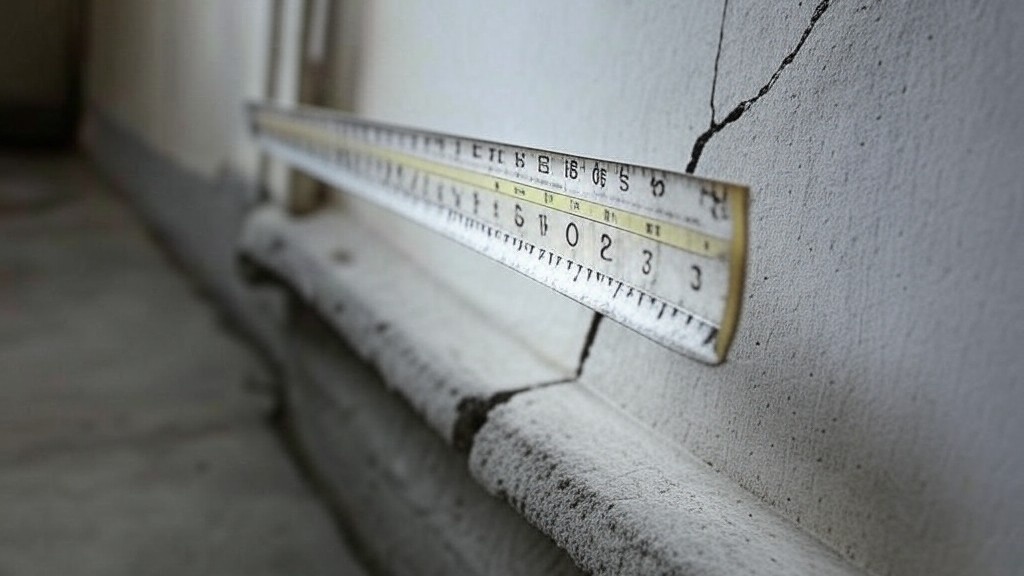
Set up crack gauges or tell-tales on adjacent structures for contractors and inspectors to establish baseline readings, install protection, and define reading frequency without including any crack repair scope.
- Plan locations, select suitable devices, and assign unique IDs.
- Install, align, and capture baseline readings with photographic evidence.
- Protect gauges, set read frequency, and define alert thresholds.
- Interactive, commentable checklist with export and QR code verification.
The checklist
Pre-Installation Planning
- Confirm monitoring scope and adjacent structures using latest drawings and precondition survey; mark proposed gauge locations on elevations with coordinates (x, y, z) in metres. Acceptance: plan approved by the engineer. Evidence: signed plan and marked-up drawings.
- Select device type (acrylic crack gauge or glass tell-tale) with range ±5 mm minimum and resolution ≤0.1 mm. Acceptance: datasheet suitability for environment (internal/external). Evidence: product datasheets and selection record.
- Assign unique ID naming convention (building-level-grid-gauge number). Acceptance: IDs unique across project. Evidence: monitoring register issued for construction.
- Verify substrate condition at each location: solid, clean, dry, and free of loose material. Acceptance: surface prepared to sound substrate; adhesion test spot passes per manufacturer guidance. Evidence: pre-install photos.
Gauge Installation
- Mark the crack centerline and gauge orientation with a fine-tip marker; establish a perpendicular datum line. Acceptance: centerline clearly visible; datum marked. Evidence: close-up photo with scale.
- Bond first plate to one side of crack using two-part epoxy adhesive (2–3 mm bed). Acceptance: plate aligned within ±1 mm of marked centerline. Evidence: photo before adhesive cures.
- Bond second plate to opposite side, aligning the reading scale at zero at ambient installation temperature. Acceptance: scale alignment tolerance ±0.5 mm. Evidence: photo showing zero alignment.
- For traditional glass tell-tales, embed glass strip over crack with plaster pads (≥70×70 mm), ensuring the crack passes under midspan. Acceptance: full contact, no rocking. Evidence: side-on and front photos.
- Label each gauge with permanent marker: ID, date, installer initials. Acceptance: label legible from 0.5 m. Evidence: labeled gauge photo.
Baseline Readings
- Allow adhesive to cure per datasheet; record cure time and ambient temperature (°C). Acceptance: minimum cure achieved before reading. Evidence: cure log entry.
- Take initial baseline reading to 0.1 mm resolution by two observers independently; average if within ±0.1 mm. Acceptance: repeatability ≤0.1 mm. Evidence: baseline photo and signed reading entry.
- Record environmental conditions: temperature (°C) and relative humidity (%) using calibrated devices (certificate ≤12 months old). Acceptance: device serial numbers logged. Evidence: instrument sticker photo.
- Capture geo-referenced context photos: close-up (≤0.3 m), mid-shot (≈1.5 m), and wide shot (≈5 m). Acceptance: ID visible in at least two photos. Evidence: three photos uploaded.
Protection and Access
- Install clear polycarbonate protective cover with standoff, keeping ≥10 mm clearance to scale for visibility. Acceptance: cover fixed without stressing gauge. Evidence: photo of cover and fixings.
- Provide weather shield for external points, UV-stable and vented to avoid condensation. Acceptance: shield secure under local wind loads. Evidence: installation photo and note.
- Place warning sign “Monitoring Point—Do Not Disturb” at ≈1.5 m height, arrowing the gauge. Acceptance: readable from 3 m. Evidence: photo from approach path.
- Establish safe access method (ladder, scaffold, or MEWP) for reading points >2.0 m. Acceptance: access equipment inspected and tagged. Evidence: access permit/tag photo.
Monitoring and Frequency
- Set reading frequency per risk and activity: e.g., daily during excavation, weekly thereafter, or as per approved project specifications and authority requirements. Acceptance: schedule approved. Evidence: issued monitoring plan.
- Define alert thresholds (e.g., >0.5 mm/day or >2.0 mm cumulative) and escalation recipients. Acceptance: thresholds documented and communicated. Evidence: sign-off on threshold memo.
- Prepare monitoring log template with fields: date/time, gauge ID, reading (mm), temperature (°C), humidity (%), notes, reader initials. Acceptance: version-controlled form. Evidence: template uploaded to CDE.
- Perform scheduled readings to 0.1 mm; two-person verification when practicable. Acceptance: difference between two reads ≤0.1 mm. Evidence: reading photo and signed log.
- Note any abnormal noise, vibration, or damage near gauges; install temporary barriers if works nearby could impact. Acceptance: barrier installed before high-risk activities. Evidence: photo and diary note.
- Trigger escalation when thresholds exceeded: notify engineer, increase frequency, and document actions. Acceptance: escalation within 24 h. Evidence: notification and action log.
Documentation and Handover
- Maintain as-built register with coordinates to ±0.1 m, building reference, level, room, and photos. Acceptance: 100% points recorded. Evidence: updated register.
- Upload daily logs and photos to the CDE with filenames: Project_GaugeID_YYYYMMDD_HHMM. Acceptance: files accessible to stakeholders. Evidence: upload report.
- Generate weekly movement graphs (mm vs time) including baseline and alerts. Acceptance: axes labelled, units SI, legend present. Evidence: exported PDF and Excel.
- Obtain review from contractor, designer, and asset owner; record comments and agreed actions. Acceptance: meeting minutes signed. Evidence: approved minutes.
- Archive calibration certificates, adhesive batch numbers, and manufacturer datasheets. Acceptance: records complete and traceable. Evidence: archive index in CDE.
Preview the printable checklist
Preview page one below. Open the image or download the PDF for all pages.

At a glance
- This checklist standardizes crack movement monitoring on adjacent structures by guiding gauge selection, precise installation, and alignment. It helps teams capture reliable baseline readings, preserve device integrity with protective measures, and formalize reading frequency to detect trends early and reduce disputes.
- It emphasizes evidence-driven documentation: geo-referenced photos, environmental conditions at each reading, calibration details, and clear IDs. The consistent data trail supports engineering decisions, stakeholder communication, and compliance with approved project specifications and authority requirements, without blending into repair activities.
- Teams receive practical cues for safe access, weather protection, and threshold-triggered escalation. Weekly summaries and exports enable quick reviews, while daily logs give granular visibility during critical phases. The result is defensible, high-quality records with minimal ambiguity and strong traceability across the project lifecycle.
- Interactive online checklist with tick, comment, and export features secured by QR code.
How to Use This Crack Gauge Setup Checklist
- Preparation: gather gauges/tell-tales, two-part epoxy, surface prep tools, thermometer/hygrometer, polycarbonate covers, labels/markers, PPE (gloves, eye protection, hard hat), ladders/MEWP as required, and approved monitoring plan.
- Site readiness: verify drawing locations, perform precondition photos, confirm access permits and equipment tags, and brief the team on IDs, tolerances, and escalation thresholds.
- Start interactive mode: open the checklist, enable ticking, and assign items. Add comments at each point for issues, photos, or deviations from the plan.
- Record baseline: complete installation steps, capture zero alignment photos, enter environmental data, and sign the baseline entries digitally for each gauge ID.
- Monitoring: follow the planned frequency, attach reading photos, and use comments to flag alerts. The system timestamps entries and links them to each gauge.
- Export and sign-off: generate PDF/Excel outputs, obtain digital signatures from responsible parties, distribute to stakeholders, and archive with QR authentication for audit.
Purpose, Scope, and Choosing the Right Gauge
Monitoring cracks on adjacent structures safeguards your works and neighbors by providing objective evidence of any movement. This checklist confines scope to crack movement monitoring only—no repair methods are included. Choose gauges or tell-tales with sufficient range and resolution to detect expected movement, and confirm suitability for indoor or outdoor conditions. Early planning sets the tone: map locations on drawings, document baseline conditions with photos, and assign unique IDs for traceability. Where cracks are irregular, align plates across the most representative segment, perpendicular to anticipated movement. Establish responsibilities and escalation pathways early so triggers are acted on promptly. Selecting devices with 0.1 mm resolution and documenting environmental conditions reduces reading noise, while a disciplined register and geo-referenced imagery make data credible and defensible across the project.
- Scope is monitoring only, not crack repair.
- Select devices with ≥±5 mm range, 0.1 mm resolution.
- Map locations and assign unique, traceable IDs.
- Document baseline photos at multiple distances.
- Define responsibilities and escalation pathways early.
Installation Best Practice and Baseline Readings
Successful monitoring depends on accurate installation. Prepare the substrate to a clean, sound surface and bond plates with an even 2–3 mm adhesive bed. Achieve near-zero alignment at installation temperature, and record curing period before taking the baseline. Use two observers to reduce human error and target ≤0.1 mm repeatability. Capture ambient temperature and humidity because environmental shifts can influence readings. Protect the device immediately after installation using clear covers and weather shields that do not load or obscure the scale. Good labels, mid-shot and wide context photos, and a complete register ensure anyone can relocate and verify each point. These basics provide stable, comparable baselines for trend analysis and reduce rework caused by disturbed or misaligned gauges.
- Align scales at zero at installation temperature.
- Achieve repeatability within ±0.1 mm for baseline.
- Record cure time and environmental conditions.
- Protect gauges without stressing the plates.
- Label clearly and photograph context.
Reading Frequency, Thresholds, and Data Management
Reading frequency should reflect construction risk. Increase frequency during high-impact activities like excavation or heavy demolition, then reduce as risk subsides, per approved project specifications and authority requirements. Define thresholds for daily and cumulative movement to trigger escalation and more frequent monitoring. Use a controlled template that records readings, environment, and notes with reader initials. Upload data daily to a common data environment, and produce weekly graphs that clearly plot movement against time and highlight alerts. Consistent filenames and geo-referenced photos speed audits and reviews. When gauges are near traffic or materials, install barriers and signage to minimize disturbances. Solid data management produces trustworthy trends and supports timely interventions if movements accelerate.
- Match reading frequency to construction risk.
- Set daily and cumulative alert thresholds.
- Use a controlled, versioned log template.
- Upload promptly and graph weekly trends.
- Protect gauges in high-traffic areas.