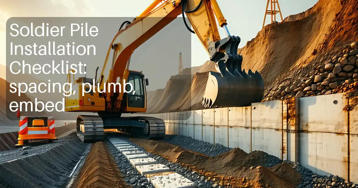
Soldier Pile Installation Checklist guides site engineers to verify spacing, plumb, embedment depth, corrosion protection, and cap details for secure, compliant foundations, excluding lagging installation activities.
- Confirm layout spacing and offsets with survey control for accurate wall lines.
- Maintain plumbness and embedment to design for stability and serviceability.
- Verify coatings, galvanic measures, and cap details to mitigate corrosion.
- Interactive, commentable workflow with evidence capture, export, and QR code.
The checklist
Pre-Installation and Materials
- Confirm latest approved drawings, geotechnical report, and method statement are on site; obtain written approvals per approved project specifications and authority requirements; file PDFs in project folder.
- Verify steel section sizes and grades for soldier piles match drawings; cross-check mill certificates and heat numbers; photograph markings and attach certs to lot record.
- Calibrate total station, digital level, inclinometer, and DFT gauge; verify certificates are in date; upload calibration proofs to checklist before work starts.
- Establish survey control and benchmarks tied to site grid; record coordinates and elevations; tolerance on control transfer ≤ ±5 mm; attach survey report and photos.
Layout and Spacing
- Set out pile centerlines using total station from control points; mark paint/pins; acceptance: centerline within ±10 mm of design; upload layout shots and CSV of points.
- Verify wall alignment and offsets from property/clearance lines; measure with total station; acceptance: offset within ±15 mm; attach plan overlay and field sketches.
- Confirm pile numbering and orientation sequence on site boards and tags; acceptance: tags legible and unique; photo evidence and supervisor signature.
- After placing each pile, measure center-to-center spacing to previous pile with total station; acceptance: spacing within ±10 mm; log readings and as‑built coordinates.
Verticality and Alignment
- Check temporary casing or guide frame verticality with dual‑axis inclinometer; acceptance: plumbness ≤ 1:200; record degrees of tilt and corrective actions.
- Monitor pile plumb during placement with digital level at two orthogonal faces; acceptance: ≤ 1:200 final; capture mid‑height and top readings with timestamped photos.
- Verify plan alignment along wall with laser/stringline; acceptance: deviation ≤ 10 mm over 10 m; record chainage and offset table; photos of line check.
- Confirm web/flange orientation per drawings for connection and lagging interfaces; use angle gauge/compass; acceptance: twist ≤ 3°; attach close‑ups of orientation marks.
Embedment and Bearing
- Measure drilled depth or driven tip elevation using sondage tape or depth counter; acceptance: tip at or below design elevation; record actual depth and elevation.
- Confirm toe stratum via driller’s log and cuttings/rock strength; obtain geotechnical witness sign‑off; acceptance: required stratum reached; attach signed log and photos.
- Record backfill concrete/grout volumes against theoretical; acceptance: variance within +10% of theoretical; attach batch tickets, delivery times, and temperature readings.
- Verify cut‑off elevation of pile head with staff and digital level; acceptance: ±5 mm; mark cut line, confirm after cut, and upload level book.
Corrosion Protection
- Inspect surface preparation grade and cleanliness before coating; verify abrasive profile with comparator; acceptance: as specified; photos before/after blasting.
- Measure dry film thickness with calibrated DFT gauge at grid points; acceptance: ≥ specified minimum at 90% readings; attach gauge log and calibration record.
- Perform holiday (pin‑hole) testing on coatings using approved detector; acceptance: zero holidays after repair; document voltage setting and re‑test results.
- Confirm specified galvanic/sacrificial measures (sleeves, caps, wraps) installed; acceptance: locations per detail; photo evidence and inspector initials.
Pile Head and Cap
- Check pile head bearing surface flatness with straightedge; acceptance: ≤ 2 mm over 300 mm; grind if needed; upload before/after photos.
- Verify cap beam reinforcement, anchor bolts, and inserts match drawings; acceptance: bar size/spacing and embedment per approved details; attach bar list and photos.
- Align base/cover plates and bolt groups using drilling template; acceptance: hole pattern within ±3 mm; measure diagonals and record as‑built.
- Confirm welding on cap plates per approved WPS; acceptance: VT free of cracks/undercut; record welder IDs, WPS number, and attach VT report.
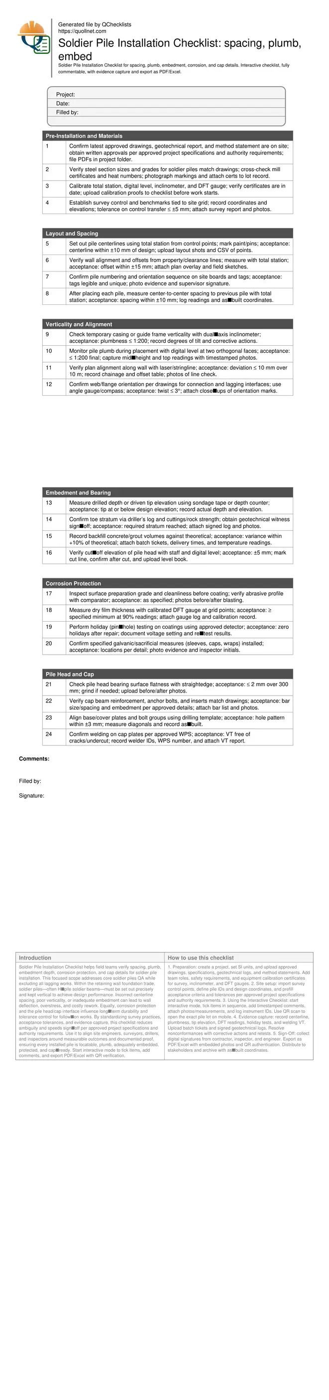
Preview the printable checklist
Preview page one below. Open the image or download the PDF for all pages.
At a glance
- Focuses on layout spacing, offsets, and verticality tolerances to achieve accurate wall alignment and minimize rework. Captures survey evidence, centerline measurements, and tip elevations so each pile’s coordinates and orientation are traceable for as‑built records.
- Controls embedment through measured depths, geotechnical confirmations, and backfill volume checks. Ensures cut‑off elevations and flat bearing surfaces, setting reliable foundations for cap works and subsequent trades without including any lagging activities.
- Strengthens durability by verifying surface preparation, coating thickness, and holiday testing, plus cap plate fit, welding documentation, and bolt pattern tolerances. Clear acceptance criteria keep inspectors and contractors aligned with project specifications.
- Interactive online checklist with tick, comment, and export features secured by QR code.
How to Use This Soldier Pile Installation Checklist
- Preparation: create a project, set SI units, and upload approved drawings, specifications, geotechnical logs, and method statements. Add team roles, safety requirements, and equipment calibration certificates for survey, inclinometer, and DFT gauges.
- Site setup: import survey control points, define pile IDs and design coordinates, and prefill acceptance criteria and tolerances per approved project specifications and authority requirements.
- Using the Interactive Checklist: start interactive mode, tick items in sequence, add timestamped comments, attach photos/measurements, and log instrument IDs. Use QR scan to open the exact pile lot on mobile.
- Evidence capture: record centerline, plumbness, tip elevation, DFT readings, holiday tests, and welding VT. Upload batch tickets and signed geotechnical logs. Resolve nonconformances with corrective actions and retests.
- Sign-Off: collect digital signatures from contractor, inspector, and engineer. Export as PDF/Excel with embedded photos and QR authentication. Distribute to stakeholders and archive with as‑built coordinates.
Layout and Spacing Control
Accurate layout is the backbone of soldier pile performance. Begin with stable survey control tied to the site grid, then set each centerline using a total station rather than tape offsets to reduce cumulative error. Mark centerlines and offsets visibly on the ground and on steel. Spacing tolerance should be tight enough to avoid downstream clashes with caps and tiebacks. After each pile is set, re‑measure center‑to‑center spacing and update an as‑built table with coordinates and elevations. Pay attention to property lines and underground constraints, validating clearances with plan overlays. Because soldier piles often sit adjacent to live infrastructure, build in a peer check before drilling or driving. Small layout deviations compound quickly along a wall, so detect drift early and correct at the next pile instead of forcing a mid‑wall bend. Document every survey check with photos and CSV exports to ensure traceability during design reviews and approvals.
- Use total station for centerlines, not tape alone.
- Hold spacing within ±10 mm to prevent cumulative drift.
- Update as‑built coordinates after each pile set.
- Validate offsets near property and utilities.
- Peer review layout before commencing production.
Verticality, Orientation, and Embedment
Verticality is critical to stiffness and wall deflection control. Use a dual‑axis inclinometer or digital level to monitor plumbness during placement, documenting readings at mid‑height and top. Maintain a practical tolerance of 1:200 or better. Confirm web orientation for connection details; even minor twist can complicate cap and tieback works. For embedment, measure drilled or driven depth and determine tip elevation against design, corroborated by driller’s logs and geotechnical witness. If the bore partially collapses, record depth immediately upon reaching design, then cross‑check backfill volumes against theoretical to validate embedment. Verify cut‑off elevation with a level and adjust by grinding or cutting to bring the pile head within tolerance. Solid evidence—photos, logs, and signatures—prevents disputes and accelerates approvals per approved project specifications and authority requirements.
- Record plumbness at two faces; target ≤ 1:200.
- Confirm web orientation within ≤ 3° twist.
- Measure tip elevation and log stratum reached.
- Validate backfill volume against theoretical.
- Check cut‑off elevation to ±5 mm.
Corrosion Protection and Cap Readiness
Durability starts with correct surface preparation and verified coating thickness. Confirm blast cleanliness and profile, then measure dry film thickness at a defined grid using a calibrated gauge. Scan for holidays with an approved detector and repair per specification before retesting. Where specified, install sleeves, wraps, or galvanic measures to protect the splash zone. At the pile head, achieve a flat bearing surface and confirm elevation ahead of cap works. Fit plates and bolt groups using templates to hold hole patterns within millimetre tolerances, and document all welding under an approved WPS with a visual examination record. These steps ensure the pile is not only structurally sound today but remains serviceable for the design life, enabling smooth integration with cap beams and follow‑on trades without rework.
- Verify surface prep grade and cleanliness.
- Measure DFT; meet specified minimum.
- Perform holiday testing and repair defects.
- Hold bolt patterns within ±3 mm.
- Document WPS, welder IDs, and VT results.