Remove Weak/Contaminated Head Concrete Verification Checklist
Definition: Remove weak/contaminated head concrete verification checklist for site supervisors and inspectors, defining non-destructive checks, acceptance cues, and documentation before authorizing controlled removal.
- Map defects and weak zones with practical field tests and photos.
- Reduce rework by setting clear, defensible removal boundaries.
- Standardize decisions using rebound, pull-off, and chemical checks.
- Interactive, commentable workflow with export and QR code verification.
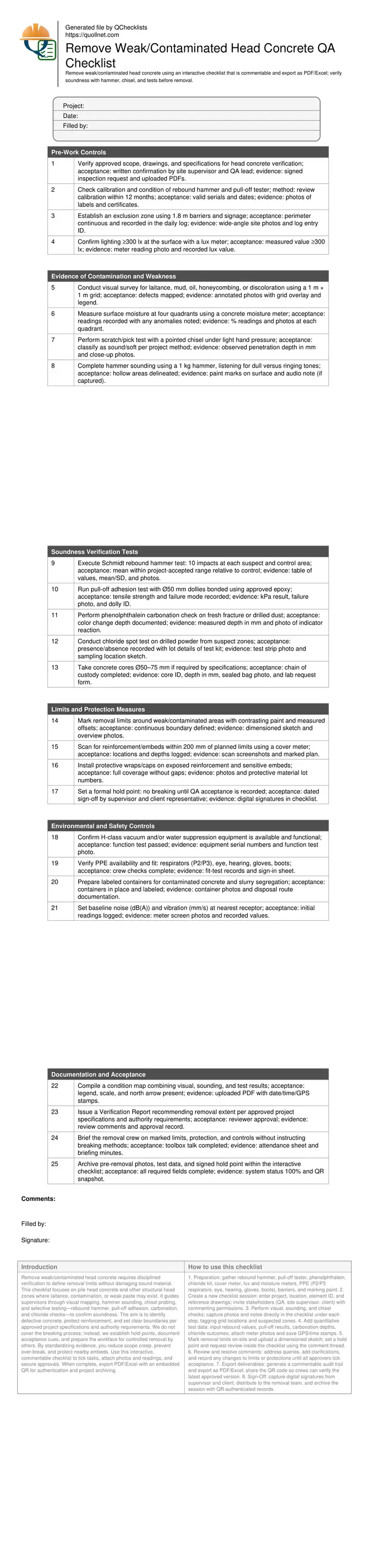
Remove weak/contaminated head concrete requires disciplined verification to define removal limits without damaging sound material. This checklist focuses on pile head concrete and other structural head zones where laitance, contamination, or weak paste may exist. It guides supervisors through visual mapping, hammer sounding, chisel probing, and selective testing—rebound hammer, pull-off adhesion, carbonation, and chloride checks—to confirm soundness. The aim is to identify defective concrete, protect reinforcement, and set clear boundaries per approved project specifications and authority requirements. We do not cover the breaking process; instead, we establish hold points, document acceptance cues, and prepare the workface for controlled removal by others. By standardizing evidence, you reduce scope creep, prevent over-break, and protect nearby embeds. Use this interactive, commentable checklist to tick tasks, attach photos and readings, and secure approvals. When complete, export PDF/Excel with an embedded QR for authentication and project archiving.
- Standardize head concrete verification using visual mapping, hammer sounding, chisel probing, and targeted tests to isolate weak or contaminated zones and prevent unnecessary over-break during subsequent removal operations.
- Define removal boundaries with measurable, photo-documented evidence so stakeholders can approve the exact extent, protect nearby reinforcement and embeds, and reduce rework and schedule delays.
- Integrate safety, environmental, and waste controls early—dust, noise, vibration, and segregation—so the workface is compliant and ready for controlled removal once authorized.
- Interactive online checklist with tick, comment, and export features secured by QR code.
Pre-Work Controls
Evidence of Contamination and Weakness
Soundness Verification Tests
Limits and Protection Measures
Environmental and Safety Controls
Documentation and Acceptance
Scope, Intent, and Boundaries
This checklist verifies weak or contaminated head concrete and defines precise removal limits, minimizing damage to sound material. It applies to pile heads, column heads, and bearing seats where laitance, mud, oils, or weak paste may compromise durability and bond. The process uses visual mapping, hammer sounding, chisel probing, and selective tests to separate defective zones from sound matrix. It protects reinforcement and adjacent embeds, and sets a formal hold point before any breaking begins. The breaking method itself is intentionally excluded; instead, the output is a documented, defensible boundary for controlled removal by the executing team, per approved project specifications and authority requirements. By standardizing evidence and approvals, the checklist reduces rework, avoids over-break, and improves downstream productivity and safety.
- Focus on verification and limits, not breaking methods.
- Use mapped evidence to prevent over-break and disputes.
- Protect reinforcement and nearby embeds before removal.
- Hold point prevents premature breaking and rework.
Field Methods to Confirm Soundness
Start with a structured visual survey using a 1 m grid to locate discoloration, laitance, honeycombing, and contamination. Follow with hammer sounding to detect hollow or delaminated zones by tone change, and chisel probing to classify paste hardness. Quantify with rebound hammer tests, comparing suspect areas to a nearby control surface of known quality. Where bonding to overlays or reinforcement is critical, use pull-off adhesion tests and record strength and failure mode. Chemical checks—phenolphthalein for carbonation depth and chloride spot tests on drilled powder—reveal hidden durability risks. Core sampling may be taken when specifications require laboratory confirmation. Record locations, measurements, and photos consistently so patterns emerge on a single condition map that stakeholders can trust.
- Always compare suspect readings to a control area.
- Record means, deviations, and failure modes.
- Log depths and locations in millimetres on a plan.
- Photograph meters, surfaces, and marked boundaries.
Defining Limits, Protection, and Compliance
Use contrasting paint to mark the boundary of weak or contaminated areas and add measured offsets for clarity. Scan for reinforcement and embeds within 200 mm of the boundary to plan protection before removal. Establish environmental controls—H-class vacuums, water suppression, noise, and vibration monitoring—and prepare labeled containers for contaminated waste. Create a formal hold point requiring supervisor and client sign-off before any breaking starts. Compile all evidence in a single report and condition map, and brief the breaking crew on limits and protections without detailing demolition methods. This ensures compliant execution, protects structural elements, and streamlines downstream work.
- Set a documented hold point before breaking.
- Protect rebar and embeds with wraps or caps.
- Baseline dust, noise, and vibration before work.
- Issue a clear map and toolbox briefing.
How to Use This Interactive Verification Checklist
- Preparation: gather rebound hammer, pull-off tester, phenolphthalein, chloride kit, cover meter, lux and moisture meters, PPE (P2/P3 respirators, eye, hearing, gloves, boots), barriers, and marking paint.
- Create a new checklist session: enter project, location, element ID, and reference drawings; invite stakeholders (QA, site supervisor, client) with commenting permissions.
- Perform visual, sounding, and chisel checks; capture photos and notes directly in the checklist under each step, tagging grid locations and suspected zones.
- Add quantitative test data: input rebound values, pull-off results, carbonation depths, chloride outcomes; attach meter photos and save GPS/time stamps.
- Mark removal limits on-site and upload a dimensioned sketch; set a hold point and request review inside the checklist using the comment thread.
- Review and resolve comments: address queries, add clarifications, and record any changes to limits or protections until all approvers tick acceptance.
- Export deliverables: generate a commentable audit trail and export as PDF/Excel; share the QR code so crews can verify the latest approved version.
- Sign-Off: capture digital signatures from supervisor and client, distribute to the removal team, and archive the session with QR-authenticated records.
Call to Action
- Start Checklist Tick off tasks, leave comments on items or the whole form, and export your completed report to PDF or Excel—with a built-in QR code for authenticity.
- Download Excel - Head Concrete Soundness Verification & Removal Limits
- Download PDF - Head Concrete Soundness Verification & Removal Limits
- View Image - Head Concrete Soundness Verification & Removal Limits
Cite & Embed
“Head Concrete Soundness Verification & Removal Limits by Quollnet”
with a link to
this source page.

FAQ
Question: What qualifies as weak or contaminated head concrete?
Question: Which verification tests should I prioritize on site?
Question: How do I decide the exact removal limits without over-breaking?
Question: Can I rely on rebound hammer results on rough or laitance-covered surfaces?
Question: How do I protect reinforcement and embeds during verification?
Related Articles
Broader reading and guidance connected to this checklist topic.


Is It Important To Customize Your Qr Code And How To Do It?

Related Checklists
Keep the workflow moving with nearby templates chosen from similar checklist content.