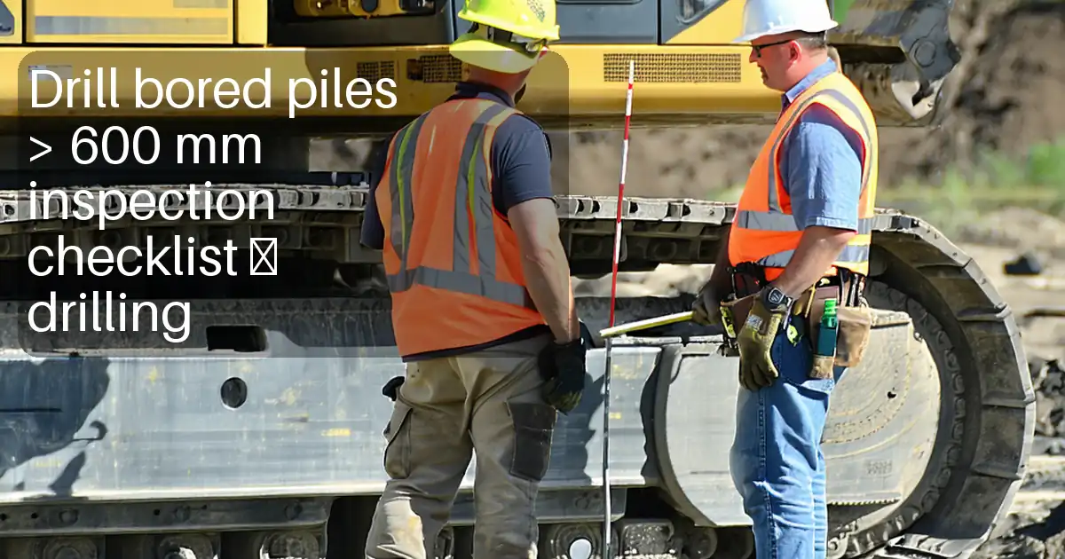
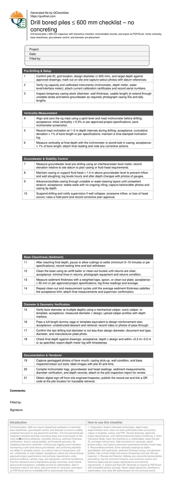
Drill bored piles ≤ 600 mm checklist – no concreting
Definition: Drill bored piles ≤ 600 mm inspection checklist equips site engineers to verify verticality, base cleanliness, groundwater control, and diameter before concreting, per approved project specifications and authority requirements.
- Confirm pile verticality with calibrated inclinometer within specified tolerances.
- Demonstrate clean base with measured sediment thickness below limit.
- Control groundwater using casing or fluid head to prevent collapse.
- Interactive, commentable, export, QR code for traceable field records.
Drill bored piles ≤ 600 mm require disciplined verification of verticality, base cleanliness, groundwater control, and diameter to ensure a stable, compliant bore prior to any placement activities. This focused bored pile inspection checklist excludes concreting steps and concentrates on the most risk‑sensitive attributes: verticality checking, sediment thickness confirmation, fluid or casing stability, and borehole geometry. By validating instrument calibration, continuously logging mast inclination, maintaining a safe head above groundwater, and confirming diameter via caliper or template checks, you reduce risks of misalignment, soft toe, underbreak, or wall collapse. Acceptance criteria are referenced per approved project specifications and authority requirements, while practical evidence—photos, logs, and signatures—confirms compliance. Use this interactive tool to standardize quality outcomes, avoid rework, and provide transparent, auditable records for stakeholders. Start in interactive mode to tick items, add comments for variances, and export as PDF/Excel with an embedded QR to authenticate field data.
- Purpose-built checklist for small-diameter bored piles that validates the four critical factors—verticality, base cleanliness, groundwater stability, and diameter—before any placement, minimizing rework and structural risks through calibrated methods and objective evidence.
- Practical, tool-specific actions show how to measure inclination at intervals, maintain a safe head over groundwater, clean and gauge sediment thickness, and verify diameter at depth, producing consistent results across crews and shifts.
- Documentation-first approach captures inclinometer logs, depth and level readings, sediment measurements, caliper profiles, and geotagged photos; clear acceptance cues reference approved project specifications and authority requirements for defensible QA decisions.
- Interactive online checklist with tick, comment, and export features secured by QR code.
Pre-Drilling & Setup
Verticality Measurement
Groundwater & Stability Control
Base Cleanliness (Sediment)
Diameter & Geometry Verification
Documentation & Handover
Controlling and Verifying Verticality
Vertical alignment is the foundation of bored pile performance. Begin by leveling the rig and zeroing the mast inclinometer before cutting ground. Track inclination at 1–2 m intervals; small corrections early prevent compounding deviations. Where soils vary, reduce crowd and torque to avoid drift. At full depth, recheck verticality using the mast instrument or a plumb line inside casing. Many projects accept ≤ 1% of bore length, but always apply the approved project specifications and authority requirements. If readings approach limits, adjust the mast and redrill/ream sections while maintaining bore stability. Capture screenshots of inclinometer readings with timestamps and pile ID to create a defensible audit trail. Consistent verticality control reduces bending demands on the pile and facilitates accurate cage placement in subsequent operations.
- Zero inclinometer and verify with a spirit level.
- Measure at 1–2 m intervals; log continuously.
- Target ≤ 1% deviation or per specifications.
- Correct early to prevent cumulative drift.
- Attach time-stamped screenshots and pile ID.
Groundwater Management and Bore Stability
Small-diameter bores are sensitive to groundwater inflow and wall sloughing. Establish the groundwater level before drilling and plan casing or support fluid accordingly. Maintain at least 1.0 m head above groundwater to create a stabilizing pressure differential. Where soils ravel or seepage increases, advance casing to a competent layer and oscillate to cut in cleanly. Monitor for signs of instability: turbid returns, loss of head, deformation at the mouth, or tool binding. Stop and escalate if collapse is suspected. Stability checks must be recorded, including water levels relative to datum, casing tip depth, and photographs of gauges. The objective is a stable, open hole with intact sidewalls ready for subsequent operations without introducing fines or soft pockets at the base.
- Measure baseline groundwater with an interface meter.
- Maintain casing/fluid head ≥ 1.0 m above groundwater.
- Advance casing through unstable layers as required.
- Stop and escalate on signs of collapse.
- Log levels, casing depth, and photo evidence.
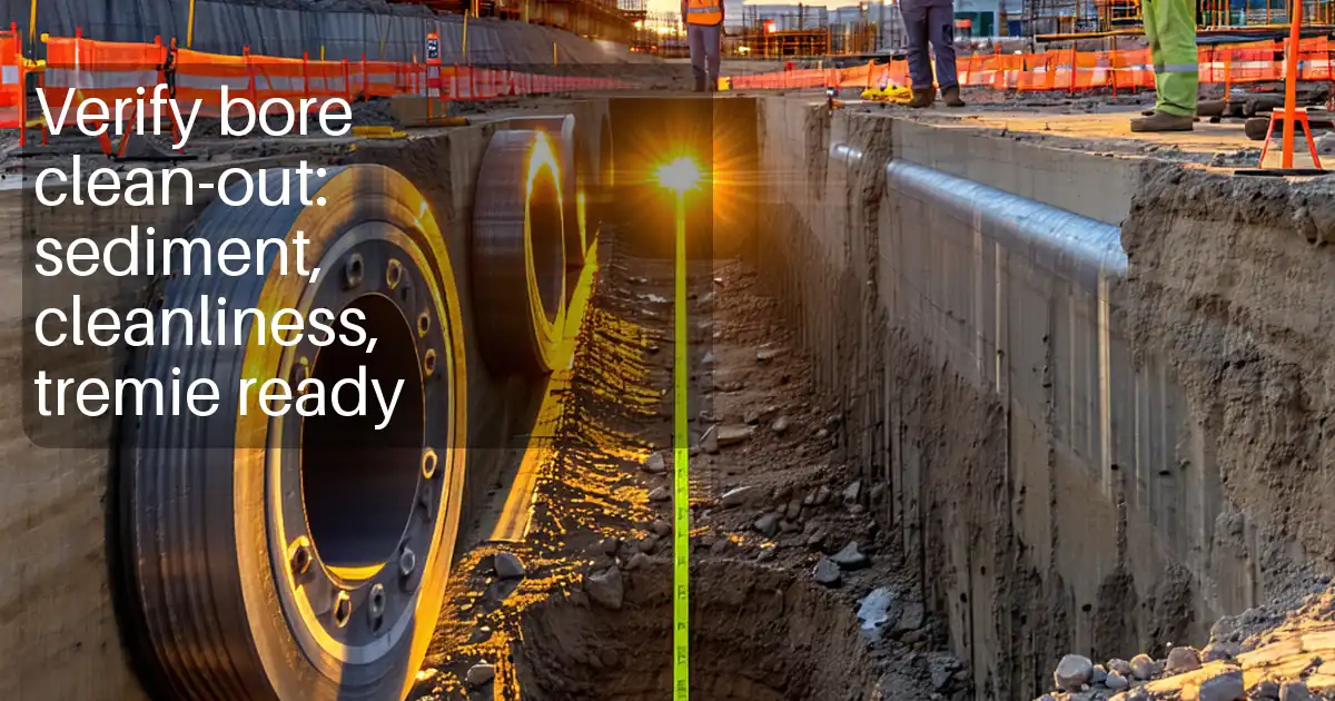
Base Cleanliness and Sediment Thickness
A clean base ensures load transfer to competent strata. After reaching depth, let cuttings settle, then use an airlift bailer or clean-out bucket to remove fines. Confirm cleanliness by measuring sediment thickness with a weighted tape, spoon, or plate. Many projects limit residual sediment to ≤ 50 mm, but always apply the approved project specifications. Take three readings at the base and average them; repeat clean-out cycles until within the acceptance limit. Document the process with photos of returns, tools used, and the measurement method. Clear, repeatable measurements reduce soft toe risk, improve end-bearing reliability, and provide transparent evidence for acceptance prior to any placement activities.
- Allow settling before clean-out begins.
- Clean using bailer or clean-out bucket.
- Measure and average three sediment readings.
- Target ≤ 50 mm or per specifications.
- Attach photos of tools and readings.
Diameter and Geometry Confirmation
Verifying bore diameter and geometry in small piles avoids underbreak and obstructions. Use a mechanical or sonic caliper to profile diameter at several depths. Measurements should meet or exceed the design diameter; underbreak is unacceptable, while overbreak must remain within project limits. Pass a dummy cage or template matching reinforcement dimensions to confirm unobstructed descent, indicating proper alignment and no local necking. Record the last drilling tool diameter and confirm it is not smaller than design. Verify final depth meets drawings within the specified tolerance. Compile caliper logs, pass-through evidence, and depth records to demonstrate the bore is dimensionally compliant and ready for subsequent steps.
- Profile diameter at multiple depths.
- Measured diameter must meet or exceed design.
- Pass a dummy cage without obstruction.
- Confirm final depth within tolerance.
- Archive caliper logs and pass-through media.
How to Use This Checklist On Site
- Preparation: Gather calibrated inclinometer, depth meter, water/interface level, clean-out tools (airlift bailer/clean-out bucket), caliper or template, casing, and PPE. Review drawings, approved project specifications, and method statements before mobilizing.
- Start Interactive Mode: Open the checklist on a mobile/tablet, select the pile ID, and begin ticking items. Add comments for variances, attach photos/videos, and capture instrument screenshots directly in each step.
- Record Measurements: Enter verticality readings by depth, groundwater and head levels, sediment thickness values, and diameter profiles. Use numeric fields and ensure timestamps and user IDs are captured.
- Review and Resolve: Address any nonconformances before proceeding. Use the comment thread to note corrective actions and reference approvals per project specifications and authority requirements.
- Export and Sign-Off: Generate an export as PDF/Excel with embedded photos and logs. Obtain digital signatures, distribute to stakeholders, and verify QR authentication for the archived record.
Call to Action
- Start Checklist Tick off tasks, leave comments on items or the whole form, and export your completed report to PDF or Excel—with a built-in QR code for authenticity.
- Download Excel - Drill Bored Piles ≤600 mm Inspection (No Concreting)
- Download PDF - Drill Bored Piles ≤600 mm Inspection (No Concreting)
- View Image - Drill Bored Piles ≤600 mm Inspection (No Concreting)
Cite & Embed
“Drill Bored Piles ≤600 mm Inspection (No Concreting) by Quollnet”
with a link to
this source page.
FAQ
Question: What verticality tolerance should I apply for bored piles up to 600 mm?
Question: How do I confirm the base is clean enough before continuing work?
Question: What is the best way to verify diameter in a small borehole?
Question: How should groundwater be managed if inflow increases during drilling?
Question: What evidence should be captured for audit and handover?
Related Articles
Broader reading and guidance connected to this checklist topic.


Related Checklists
Keep the workflow moving with nearby templates chosen from similar checklist content.